HP Spectre Notebook PC * Model numbers 13-v000 through 13-v099 HP Spectre Pro13 G1 Notebook PC Maintenance and Service Guide
© Copyright 2016 HP Development Company, L.P. AMD is a trademark of Advanced Micro Devices, Inc. Bluetooth is a trademark owned by its proprietor and used by HP Inc. under license. Intel, Celeron, and Pentium are trademarks of Intel Corporation in the U.S. and other countries. Microsoft and Windows are U.S. registered trademarks of the Microsoft group of companies.
Safety warning notice WARNING! To reduce the possibility of heat-related injuries or of overheating the device, do not place the device directly on your lap or obstruct the device air vents. Use the device only on a hard, flat surface. Do not allow another hard surface, such as an adjoining optional printer, or a soft surface, such as pillows or rugs or clothing, to block airflow. Also, do not allow the AC adapter to contact the skin or a soft surface, such as pillows or rugs or clothing, during operation.
iv Safety warning notice
Table of contents 1 Product description ....................................................................................................................................... 1 2 External component identification .................................................................................................................. 4 Locating hardware .................................................................................................................................................
Speakers ............................................................................................................................................ 31 TouchPad board ................................................................................................................................. 32 Fan ..................................................................................................................................................... 33 System board .........................................
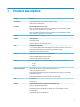
1 Product description Category Description Product Name HP Spectre Notebook PC (model numbers 13-v000 – 13-v099) HP Spectre Pro13 G1 Notebook PC Processors 6th generation Intel® Core™ Processor Intel Core i7-6500U 2.50-GHz (SC turbo up to 3.10-GHz) processor (1866-MHz FSB, 4.0-MB L3 cache, dual core, 15-W [dynamic PL1 to 8.5-10 W]) Intel Core i5-6200U 2.30-GHz (SC turbo up to 2.80-GHz) processor (1866-MHz FSB, 3.0-MB L3 cache, dual core, 15-W [dynamic PL1 to 8.
Category Description Internal card expansion One M.2 slot for solid-state drive Ports Hot plug/unplug and auto detect for correct output to wide-aspect vs. standard aspect video (auto adjust panel resolution to fit embedded panel and external monitor connected) Headphone/microphone combo USB Type-C ports on unit: Keyboard/pointing devices ● (2) USB 3.1 Gen 2 with Thunderbolt™ Gen 3 technology - rear, middle ● (1) USB 3.1 Gen 1 (i.e. USB 3.
Category Description Windows 10 Professional 64 Windows 10 Home 64 High End Windows 10 Home 64 High Single Language Windows 10 Home 64 Chinese Market – CPPP Restore media (HP Spectre Pro13 G1 models): Windows 10 SSRU Windows 10 SSRD Certified (HP Spectre Pro13 G1 models): Microsoft WHQL: Win 10 64 Serviceability End user replaceable part: AC adapter 3
2 External component identification Locating hardware To find out what hardware is installed on your computer: ▲ Type device manager in the taskbar search box, and then select the Device Manager app. A list displays all the devices installed on your computer. For information about system hardware components and the system BIOS version number, press fn+esc (select products only).
Display Component Description (1) WLAN antennas* Send and receive wireless signals to communicate with wireless local area networks (WLANs). (2) Internal microphones (2) Record sound. (3) Webcam light On: The webcam is in use. (4) Webcam Records video and captures photographs. Some products allow you to video conference and chat online using streaming video. To use a webcam (integrated camera): ▲ Type camera in the taskbar search box, and then select Camera.
Top TouchPad Component 6 Description (1) TouchPad zone Reads your finger gestures to move the pointer or activate items on the screen. (2) Left TouchPad button Functions like the left button on an external mouse. (3) Right TouchPad button Functions like the right button on an external mouse.
Lights Component (1) Description Power light ● On: The computer is on. ● Blinking: The computer is in the Sleep state, a powersaving state. The computer shuts off power to the display and other unneeded components. ● Off: The computer is off or in Hibernation. Hibernation is a power-saving state that uses the least amount of power. (2) Caps lock light On: Caps lock is on, which switches the key input to all capital letters. (3) Mute light ● Amber: Computer sound is off.
Button and speakers Component (1) Description Power button ● When the computer is off, press the button to turn on the computer. ● When the computer is on, press the button briefly to initiate Sleep. ● When the computer is in the Sleep state, press the button briefly to exit Sleep. ● When the computer is in Hibernation, press the button briefly to exit Hibernation. CAUTION: Pressing and holding down the power button results in the loss of unsaved information.
Keys Component Description (1) esc key Displays system information when pressed in combination with the fn key. (2) fn key Executes frequently used system functions when pressed in combination with the esc key or one of the action keys. (3) Windows key Opens the Start menu. NOTE: Pressing the Windows key again will close the Start menu. (4) Action keys Execute frequently used system functions. NOTE: On select products, the f5 action key turns the keyboard backlight feature off or on.
Using the action keys ● An action key performs an assigned function. ● The icon on each action key illustrates the function for that key. ● To use an action key, press and hold the key. Icon Description Decreases the screen brightness incrementally as long as you hold down the key. Increases the screen brightness incrementally as long as you hold down the key. Switches the screen image between display devices connected to the system.
Rear side Component (1) (2) Description AC adapter and battery light USB Type-C power connector and charging port ● White: The AC adapter is connected and the battery is fully charged. ● Blinking white: The AC adapter is disconnected and the battery has reached a low battery level. ● Amber: The AC adapter is connected and the battery is charging. ● Off: The battery is not charging.
Bottom Component Description Vents (4) Enable airflow to cool internal components. NOTE: The computer fan starts up automatically to cool internal components and prevent overheating. It is normal for the internal fan to cycle on and off during routine operation.
Service tag When ordering parts or requesting information, provide the computer serial number and model number provided on the service tag. Item Description Function (1) Product name This is the product name affixed to the front of the computer. (2) Serial number (s/n) This is an alphanumeric identifier that is unique to each product. (3) Part number/Product number (p/n) This number provides specific information about the product's hardware components.
3 Illustrated parts catalog NOTE: HP continually improves and changes product parts. For complete and current information on supported parts for your computer, go to http://partsurfer.hp.com, select your country or region, and then follow the on-screen instructions.
Item Component Spare part number (1) Display assembly with keyboard and top cover 855641-xx1 NOTE: For a list of keyboard country codes, see Display assembly, top cover, keyboard on page 40.
Item Component Spare part number (13) 3-cell, 45-Wh, 3.
Miscellaneous parts Component Spare part number 45-W Smart adapter, wall mount, USB-C For use in HP Spectre Pro13 G1 Notebook PC models 848293-850 For use in HP Spectre Notebook PC models 860210-850 Adapter USB-C to USB-A 833960-001 USB-C to VGA 831751-001 USB-C to HDMI 831752-001 USB-C to DisplayPort 831753-001 USB-C to RJ-45 Gigabit 855560-001 Power cord (1.
18 Component Spare part number HP Business Backpack 718548-001 HP Business Slim Load Top Case 718549-001 Chapter 3 Illustrated parts catalog
4 Removal and replacement procedures preliminary requirements Tools required You will need the following tools to complete the removal and replacement procedures: ● Case utility tool or similar plastic, flat-tipped tool ● Flat-bladed screwdriver ● Magnetic screwdriver ● Phillips P0 and P1 screwdrivers Service considerations The following sections include some of the considerations that you must keep in mind during disassembly and assembly procedures.
Cables and connectors CAUTION: When servicing the computer, be sure that cables are placed in their proper locations during the reassembly process. Improper cable placement can damage the computer. Cables must be handled with extreme care to avoid damage. Apply only the tension required to unseat or seat the cables during removal and insertion. Handle cables by the connector whenever possible. In all cases, avoid bending, twisting, or tearing cables.
Grounding guidelines Electrostatic discharge damage Electronic components are sensitive to electrostatic discharge (ESD). Circuitry design and structure determine the degree of sensitivity. Networks built into many integrated circuits provide some protection, but in many cases, ESD contains enough power to alter device parameters or melt silicon junctions. A discharge of static electricity from a finger or other conductor can destroy static-sensitive devices or microcircuitry.
Packaging and transporting guidelines Follow these grounding guidelines when packaging and transporting equipment: ● To avoid hand contact, transport products in static-safe tubes, bags, or boxes. ● Protect ESD-sensitive parts and assemblies with conductive or approved containers or packaging. ● Keep ESD-sensitive parts in their containers until the parts arrive at static-free workstations. ● Place items on a grounded surface before removing items from their containers.
Equipment guidelines Grounding equipment must include either a wrist strap or a foot strap at a grounded workstation. ● When seated, wear a wrist strap connected to a grounded system. Wrist straps are flexible straps with a minimum of one megohm ±10% resistance in the ground cords. To provide proper ground, wear a strap snugly against the skin at all times. On grounded mats with banana-plug connectors, use alligator clips to connect a wrist strap.
5 Removal and replacement procedures for Authorized Service Provider parts CAUTION: Components described in this chapter should only be accessed by an authorized service provider. Accessing these parts can damage the computer or void the warranty. NOTE: HP continually improves and changes product parts. For complete and current information on supported parts for your computer, go to http://partsurfer.hp.com, select your country or region, and then follow the on-screen instructions.
3. Remove the five Phillips PM2.0×5.0 screws (2) that secure the bottom cover to the computer. 4. Use a case utility tool or similar plastic, flat-tipped tool to separate the left edge of the bottom cover from keyboard/top cover (1). 5. Separate the front edge (2) and the right edge (3) of the bottom cover from keyboard/top cover. 6. Remove the bottom cover (4). Reverse this procedure to install the bottom cover.
Battery Description Spare part number 3-cell, 45-Wh, 3.83-Ah, Li-ion battery 844199-855 Before removing the battery, follow these steps: 1. Turn off the computer. If you are unsure whether the computer is off or in Hibernation, turn the computer on, and then shut it down through the operating system. 2. Disconnect the power from the computer by unplugging the power cord from the computer. 3. Disconnect all external devices from the computer. 4.
6. Remove the battery (4). Reverse this procedure to install the battery.
Solid-state drive Description Spare part number Solid-state drive for use in HP Spectre Notebook PC models (PCIe, M.2, NVMe, TLC) 1-TB, PCIe 912677-001 512-GB 855609-001 256-GB 855608-001 Solid-state drive for use in HP Spectre Pro13 G1 Notebook PC models (PCIe, M.2, NVMe, TLC) 512-GB 900890-001 256-GB 900889-001 Solid-state drive bracket (included in Bracket Kit) 904845-001 Before removing the solid-state drive, follow these steps: 1. Turn off the computer.
WLAN module Description Spare part number WLAN board (for use in HP Spectre Notebook PC models) 855631-001 Intel Dual band wireless-AC 8260 802.11ac 2x2 WiFi + BT 4.
NOTE: The WLAN antenna cable labeled “1/MAIN” connects to the WLAN module “Main” terminal. The WLAN antenna cable labeled “2/AUX” connects to the WLAN module “Aux” terminal. 5. Lift the module out of the socket (2). NOTE: If the WLAN antennas are not connected to the WLAN module, the protective sleeve should be installed on the antenna connectors, as shown in the following illustration. Reverse this procedure to install the WLAN module.
Speakers Description Spare part number Right speaker 855633-001 Left speaker 855634-001 Before removing the speakers, follow these steps: 1. Turn off the computer. If you are unsure whether the computer is off or in Hibernation, turn the computer on, and then shut it down through the operating system. 2. Disconnect the power from the computer by unplugging the power cord from the computer. 3. Disconnect all external devices from the computer. 4.
TouchPad board Description Spare part number TouchPad board 855632-001 Before removing the TouchPad board, follow these steps: 1. Turn off the computer. If you are unsure whether the computer is off or in Hibernation, turn the computer on, and then shut it down through the operating system. 2. Disconnect the power from the computer by unplugging the power cord from the computer. 3. Disconnect all external devices from the computer. 4. Remove the bottom cover (see Bottom cover on page 24). 5.
Fan Description Spare part number Fans (includes left and right fans) 855629-001 Before removing the fans, follow these steps: 1. Turn off the computer. If you are unsure whether the computer is off or in Hibernation, turn the computer on, and then shut it down through the operating system. 2. Disconnect the power from the computer by unplugging the power cord from the computer. 3. Disconnect all external devices from the computer. 4. Remove the bottom cover (see Bottom cover on page 24). 5.
2. To remove the right fan, disconnect the fan cables from the system board (1), remove the two Phillips PM2.0×3.0 screws (2), and then lift the fan at an angle (approximately 45 degrees) and pull it out from under the edge of the computer (3). Reverse this procedure to install the fans.
System board Description Spare part number Equipped with an Intel Core i7-6500U 2.50-GHz processor, 8 GB of system RAM, and the Windows 10 Professional operating system 854753-601 Equipped with an Intel Core i7-6500U 2.50-GHz processor, 8 GB of system RAM, and a nonWindows operating system 854753-001 Equipped with an Intel Core i5-6200U 2.30-GHz processor, 8 GB of system RAM, and the Windows 10 Professional operating system 860825-601 Equipped with an Intel Core i5-6200U 2.
2. Remove the three Phillips PM2.0×3.0 screws (1) that secure the system board to the computer. 3. Swing the rear edge of the system board up and forward so you can access the RTC battery cable underneath (2). 4. Disconnect the RTC battery cable (3) from the system board. 5. Remove the system board (4). Reverse this procedure to install the system board.
Heat sink Description Spare part number Heat sink (includes replacement thermal material) 854752-001 Before removing the heat sink, follow these steps: 1. Turn off the computer. If you are unsure whether the computer is off or in Hibernation, turn the computer on, and then shut it down through the operating system. 2. Disconnect the power from the computer by unplugging the power cord from the computer. 3. Disconnect all external devices from the computer. 4.
Reverse this procedure to install the heat sink.
Cable locations Description Spare part number TouchPad cable 855627-001 WLAN board cable 855628-001 Use the following image to determine proper cable routing.
Display assembly, top cover, keyboard The display assembly is spared with the top cover and keyboard as one whole component. Individual display components are not spared.
6 Using Setup Utility (BIOS) in Windows 10 Setup Utility, or Basic Input/Output System (BIOS), controls communication between all the input and output devices on the system (such as disk drives, display, keyboard, mouse, and printer). Setup Utility (BIOS) includes settings for the types of devices installed, the startup sequence of the computer, and the amount of system and extended memory.
Downloading a BIOS update CAUTION: To reduce the risk of damage to the computer or an unsuccessful installation, download and install a BIOS update only when the computer is connected to reliable external power using the AC adapter. Do not download or install a BIOS update while the computer is running on battery power, docked in an optional docking device, or connected to an optional power source.
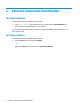
7 Using HP PC Hardware Diagnostics (UEFI) HP PC Hardware Diagnostics is a Unified Extensible Firmware Interface (UEFI) that allows you to run diagnostic tests to determine whether the computer hardware is functioning properly. The tool runs outside the operating system so that it can isolate hardware failures from issues that are caused by the operating system or other software components.
3. Enter the product name or number. – or – Select Identify now to let HP automatically detect your product. 44 4. Select your computer, and then select your operating system. 5. In the Diagnostic section, follow the on-screen instructions to select and download the UEFI version you want.
8 Backing up, restoring, and recovering in Windows 10 This chapter provides information about the following processes. The information in the chapter is standard procedure for most products. ● Creating recovery media and backups ● Restoring and recovering your system For additional information, refer to the HP support assistant app. ▲ Type support in the taskbar search box, and then select the HP Support Assistant app. ‒ or – Click the question mark icon in the taskbar.
You can use Windows tools to create system restore points and create backups of personal information, see Using Windows tools on page 46. ● If your computer does list the Recovery partition and the Windows partition, you can use HP Recovery Manager to create recovery media after you successfully set up the computer. HP Recovery media can be used to perform system recovery if the hard drive becomes corrupted.
Restore and recovery There are several options for recovering your system. Choose the method that best matches your situation and level of expertise: IMPORTANT: ● Windows offers several options for restoring from backup, refreshing the computer, and resetting the computer to its original state. For more information see the Get started app. ▲ ● Not all methods are available on all products. Select the Start button, and then select the Get started app.
website. Go to http://www.hp.com/support, select your country or region, and follow the on-screen instructions. IMPORTANT: HP Recovery Manager does not automatically provide backups of your personal data. Before beginning recovery, back up any personal data you want to retain. Using HP Recovery media, you can choose from one of the following recovery options: NOTE: Only the options available for your computer display when you start the recovery process.
Changing the computer boot order If your computer does not restart in HP Recovery Manager, you can change the computer boot order, which is the order of devices listed in BIOS where the computer looks for startup information. You can change the selection to an optical drive or a USB flash drive. To change the boot order: IMPORTANT: For a tablet with a detachable keyboard, connect the keyboard to the keyboard dock before beginning these steps. 1. Insert the HP Recovery media. 2.
9 Specifications Computer specifications The computer operates on DC power, which can be supplied by an AC or a DC power source. The AC power source must be rated at 100–240 V, 50–60 Hz. Although the computer can be powered from a standalone DC power source, it should be powered only with an AC adapter or a DC power source that is supplied and approved by HP for use with this computer. Metric U.S. Width 32.5 cm 12.80 in Depth 22.9 cm 9.02 in Height 1.0 cm 0.39 in Weight 1.63 kg 3.
10 Power cord set requirements The wide-range input feature of the computer permits it to operate from any line voltage from 100 to 120 volts AC, or from 220 to 240 volts AC. The 3-conductor power cord set included with the computer meets the requirements for use in the country or region where the equipment is purchased. Power cord sets for use in other countries and regions must meet the requirements of the country or region where the computer is used.
52 Country/region Accredited agency Applicable note number Sweden SEMKO 1 Switzerland SEV 1 Taiwan BSMI 4 The United Kingdom BSI 1 The United States UL 2 1. The flexible cord must be Type HO5VV-F, 3-conductor, 1.0-mm² conductor size. Power cord set fittings (appliance coupler and wall plug) must bear the certification mark of the agency responsible for evaluation in the country or region where it will be used. 2. The flexible cord must be Type SPT-3 or equivalent, No.
11 Recycling When a non-rechargeable or rechargeable battery has reached the end of its useful life, do not dispose of the battery in general household waste. Follow the local laws and regulations in your area for battery disposal. HP encourages customers to recycle used electronic hardware, HP original print cartridges, and rechargeable batteries. For more information about recycling programs, see the HP Web site at http://www.hp.com/recycle.
Index A AC adapter and battery 11 AC adapter, spare part numbers 17 action keys 10 identifying 9 adapter, spare part numbers 17 airplane mode key 10 audio, product description 1 audio-out (headphone)/audio-in (microphone) jack, identifying 11 B backups 45 battery removal 26 spare part number 16, 26 BIOS determining version 41 downloading an update 42 starting the Setup Utility 41 updating 41 boot order changing 49 bottom cover removal 24 spare part numbers 16, 24 buttons left TouchPad 6 power 8 right TouchP
P pointing device, product description 2 ports product description 2 USB Type-C power connector and charging 11 USB Type-C power connector and Thunderbolt port 11 power button, identifying 8 power connector, identifying 11 power cord set requirements 51 spare part numbers 17 power lights, identifying 7 power requirements, product description 2 processor, product description 1 product description audio 1 chipset 1 display panel 1 graphics 1 internal card expansion 2 keyboard 2 memory module 1 microphone 1 op