HP Pavilion x360 Convertible PC (model numbers 15-bk100 through 15bk199 and 15-bk000 through 15-bk099) Maintenance and Service Guide IMPORTANT! This document is intended for HP authorized service providers only.
© Copyright 2016 HP Development Company, L.P. Product notice Bluetooth is a trademark owned by its proprietor and used by HP Inc. under license. Intel, Core, and Pentium are U.S. registered trademarks of Intel Corporation. Microsoft and Windows are either registered trademarks or trademarks of Microsoft Corporation in the United States and/or other countries. SD Logo is a trademark of its proprietor. This guide describes features that are common to most models.
Safety warning notice WARNING! To reduce the possibility of heat-related injuries or of overheating the device, do not place the device directly on your lap or obstruct the device air vents. Use the device only on a hard, flat surface. Do not allow another hard surface, such as an adjoining optional printer, or a soft surface, such as pillows or rugs or clothing, to block airflow. Also, do not allow the AC adapter to contact the skin or a soft surface, such as pillows or rugs or clothing, during operation.
iv Safety warning notice
Table of contents 1 Product description ....................................................................................................................................... 1 2 External component identification .................................................................................................................. 5 Locating hardware .................................................................................................................................................
Hard drive .......................................................................................................................................... 35 RTC battery ........................................................................................................................................ 36 WLAN module .................................................................................................................................... 37 Connector board ...........................................
Index .............................................................................................................................................................
viii
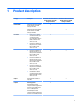
1 Product description Category Description Product Name HP Pavilion x360 Convertible PC (model numbers 15-bk100 through 15-bk199) HP Pavilion x360 Convertible PC (model numbers 15-bk100 through 15-bk199) √ HP Pavilion x360 Convertible PC (model numbers 15-bk000 through 15-bk099) Processors ● Intel® Core™ i5-7200U 2.50-GHz (SC turbo up to 3.10-GHz) processor (2133-MHz front-side bus (FSB), 3.0-MB L3 cache, dual core, 15-W) ● Intel Core i3-7100U 2.40GHz processor (2133-MHz FSB, 3.
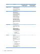
Category Description Graphics (continued) i5-6200U, Intel Core i3-6100U, or Intel Pentium processor HP Pavilion x360 Convertible PC (model numbers 15-bk100 through 15-bk199) HP Pavilion x360 Convertible PC (model numbers 15-bk000 through 15-bk099) √ √ √ √ √ √ √ √ Support for HD decode, DX12, and high-definition multimedia interface (HDMI) v1.4 Panel 15.6-in, full-high-definition (FHD), AntiGlare (AG; 1920×1080), white lightemitting diode (WLED), UWVA, embedded DisplayPort (eDP), slim-flat (3.
Category Description HP Pavilion x360 Convertible PC (model numbers 15-bk100 through 15-bk199) HP Pavilion x360 Convertible PC (model numbers 15-bk000 through 15-bk099) Optical drive Support for HP USB external DVD ±RW DL SuperMulti Drive √ √ Audio and video HP TrueVision HD webcam with indicator light, 720p by 30 frames per second, f2.
Category Description Ports (continued) ● (stereo headphone) combination ● AC Smart Pin adapter plug ● HDMI v1.4 supporting up to 1920×1080 @ 60 Hz ● RJ-45/Ethernet ● USB 3.0 (2) ● USB 2.
2 External component identification Locating hardware To find out what hardware is installed on your computer: ▲ Type device manager in the taskbar search box, and then select the Device Manager app. A list displays all the devices installed on your computer. For information about system hardware components and the system BIOS version number, press fn+esc (select products only).
Display Item Component Description (1) Internal microphones (2) Record sound. (2) Webcam light On: The webcam is in use. (3) Webcam Allows you to video chat, record video, and record still photographs. Some products also provide HD or 3D capability, apps for gaming, or facial recognition software for Windows Hello. To use the webcam: ▲ (4) WLAN antennas* Type camera in the taskbar search box, and then select Camera. Send and receive wireless signals to communicate with WLANs.
Keys Item Component Description (1) esc key Displays system information when pressed in combination with the fn key. (2) fn key Displays system information when pressed in combination with the esc key. (3) Windows key Opens the Start menu. NOTE: Pressing the Windows key again will close the Start menu. (4) Action keys Execute frequently used system functions. NOTE: On select products, the f5 action key turns the keyboard backlight feature off or on.
Lights 8 Item Component Description (1) Caps lock light On: Caps lock is on, which switches the key input to all capital letters. (2) Mute light ● Amber: Computer sound is off. ● Off: Computer sound is on.
TouchPad Item Component Description (1) TouchPad zone Reads your finger gestures to move the pointer or activate items on the screen. (2) Left TouchPad button Functions like the left button on an external mouse. (3) Right TouchPad button Functions like the right button on an external mouse.
Left side Item Component Description (1) Power button ● When the computer is off, press the button to turn on the computer. ● When the computer is on, press the button briefly to initiate Sleep. ● When the computer is in the Sleep state, press the button briefly to exit Sleep. ● When the computer is in Hibernation, press the button briefly to exit Hibernation. CAUTION: Pressing and holding down the power button results in the loss of unsaved information.
Item Component Description 2. Insert the card into the memory card reader, and then press in on the card until it is firmly seated. To remove a card: ▲ (6) Volume button Control speaker volume on the computer. ● ● (7) Drive light Press in on the card, and then remove it from the memory card reader. Notebook and interactive stand mode: ◦ To increase the volume, press the edge closest to the hinge. ◦ To decrease the volume, press the edge closest to the TouchPad.
Right side Item Component Description (1) Audio-out (headphone)/Audio-in (microphone) combo jack Connects optional powered stereo speakers, headphones, earbuds, a headset, or a television audio cable. Also connects an optional headset microphone. This jack does not support optional standalone microphones. WARNING! To reduce the risk of personal injury, adjust the volume before putting on headphones, earbuds, or a headset.
Item Component Description (7) AC adapter and battery light (continued) ● Amber: The AC adapter is connected and the battery is charging. ● Off: The battery is not charging. (8) Power connector Connects an AC adapter. Item Component Description (1) Vent Enable airflow to cool internal components. Bottom NOTE: The computer fan starts up automatically to cool internal components and prevent overheating. It is normal for the internal fan to cycle on and off during routine operation.
3 Illustrated parts catalog NOTE: HP continually improves and changes product parts. For complete and current information on supported parts for your computer, go to http://partsurfer.hp.com, select your country or region, and then follow the on-screen instructions. Locating the model number, product number, serial number, and warranty information The model number (1), product number (2), serial number (3), and warranty information (4) and are located on the bottom of the computer.
Item Description Function (3) Serial number (s/n) This is an alphanumeric identifier that is unique to each product. (4) Warranty period This number describes the duration of the warranty period for the computer.
Computer major components 16 Chapter 3 Illustrated parts catalog
Item Component Spare part number (1) Display assembly: The display assembly is spared at the subcomponent level only. For more display assembly spare part information, see Display components on page 21.
Item Component Spare part number For use in Germany 862648-041 For use in Greece 862648-151 For use in Hungary 862648-211 For use in Israel 862648-BB1 For use in Italy 862648-061 For use in the Netherlands 862648-B31 For use in Portugal 862648-131 For use in Romania 862648-271 For use in Russia 862648-251 For use in Saudi Arabia 862648-171 For use in Slovenia 862648-F81 For use in Spain 862648-071 For use in Switzerland 862648-BG1 For use in Turkey 862648-141 For use in the Un
Item Component Spare part number For use in Switzerland 862652-BG1 For use in Turkey 862652-141 For use in the United Kingdom 862652-031 For use in the United States 862652-001 (3) Power button board (includes cable and double-sided adhesive) 807528-001 (4) Power connector cable 807522-001 (5) Connector board (includes cable, memory card reader, USB port, and doublesided adhesive) 807527-001 (6) Hard drive: NOTE: The hard drive spare part kit does not include the hard drive bracket, cab
Item (9) (10) Component Spare part number Equipped with an Intel Core i5-6200U 2.30-GHz (SC turbo up to 2.80-GHz) processor (1600MHz FSB, 3.0-MB L3 cache, dual core, 15-W), an nVIDIA N16S-GM (GeForce 930M) graphics subsystem with 2048-MB of dedicated video memory, and the Windows 10 Professional operating system 863125-601 Equipped with an Intel Core i5-6200U 2.30-GHz (SC turbo up to 2.80-GHz) processor (1600MHz FSB, 3.
Item Component Spare part number Rubber Kit (not illustrated, includes base enclosure rubber feet, screw cover strips, and screw cover plugs) In cardinal red finish 862645-001 In natural silver finish 807533-001 In sport purple finish 862646-001 Display components Item Component (1) Display panel assembly (includes bezel, panel, and TouchScreen board): Spare part number 15.6-in, FHD, WLED, AntiGlare (1920×1080), slim-flat (3.2-mm), UWVA, eDP 862643-001 15.
Item Component Spare part number (4) Display hinges (2) 862642-001 Display hinge covers (2; not illustrated) 810455-001 (5) Display panel cable (includes TouchScreen board cable, adhesive support strip, and double-sided adhesive): For use only on computer models with model numbers 15-bk100 through 15-bk199 903913-001 For use only on computer models with model numbers 15-bk000 through 15-bk099 808240-001 (6) Antenna Kit (includes auxiliary antenna cables and transceivers and main antenna cables
4 Removal and replacement procedures preliminary requirements Tools required You will need the following tools to complete the removal and replacement procedures: ● Case utility tool or similar plastic, flat-edged tool ● Flat-bladed screwdriver ● Magnetic screwdriver ● Phillips P00, P0, and P1 screwdrivers ● Torx T4 screwdriver Service considerations The following sections include some of the considerations that you must keep in mind during disassembly and assembly procedures.
Drive handling CAUTION: Drives are fragile components that must be handled with care. To prevent damage to the computer, damage to a drive, or loss of information, observe these precautions: Before removing or inserting a hard drive, shut down the computer. If you are unsure whether the computer is off or in Hibernation, turn the computer on, and then shut it down through the operating system. Before handling a drive, be sure that you are discharged of static electricity.
Grounding guidelines Electrostatic discharge damage Electronic components are sensitive to electrostatic discharge (ESD). Circuitry design and structure determine the degree of sensitivity. Networks built into many integrated circuits provide some protection, but in many cases, ESD contains enough power to alter device parameters or melt silicon junctions. A discharge of static electricity from a finger or other conductor can destroy static-sensitive devices or microcircuitry.
Packaging and transporting guidelines Follow these grounding guidelines when packaging and transporting equipment: ● To avoid hand contact, transport products in static-safe tubes, bags, or boxes. ● Protect ESD-sensitive parts and assemblies with conductive or approved containers or packaging. ● Keep ESD-sensitive parts in their containers until the parts arrive at static-free workstations. ● Place items on a grounded surface before removing items from their containers.
Equipment guidelines Grounding equipment must include either a wrist strap or a foot strap at a grounded workstation. ● When seated, wear a wrist strap connected to a grounded system. Wrist straps are flexible straps with a minimum of one megohm ±10% resistance in the ground cords. To provide proper ground, wear a strap snugly against the skin at all times. On grounded mats with banana-plug connectors, use alligator clips to connect a wrist strap.
5 Removal and replacement procedures CAUTION: Components described in this chapter should only be accessed by an authorized service provider. Accessing these parts can damage the computer or void the warranty. Component replacement procedures NOTE: Details about the computer, including model, serial number, product key, and length of warranty, are on the service tag on the back of the computer. See Locating the model number, product number, serial number, and warranty information on page 14 for details.
For use in country Spare part number For use in country Spare part number For use in the Czech Republic and Slovakia 862648-FL1 For use in Russia 862648-251 For use in Denmark, Finland, and Norway 862648-DH1 For use in Saudi Arabia 862648-171 For use in France 862648-051 For use in Slovenia 862648-F81 For use in Germany 862648-041 For use in Spain 862648-071 For use in Greece 862648-151 For use in Switzerland 862648-BG1 For use in Hungary 862648-211 For use in Turkey 862648-141 F
5. Remove the two screw cover plugs (3). The computer feet, screw cover strips, and screw cover plugs are included in the Rubber Kits, using the following spare part numbers: 30 ● 862645-001 – In cardinal red finish ● 807533-001 – In natural silver finish ● 862646-001 – in sport purple finish 6. Remove the twelve Phillips M2.5×7.0 screws that secure the keyboard/top cover to the computer. 7. Turn the computer right side up with the front toward you. 8. Open the computer.
9. Insert a case utility tool (1) or similar plastic, flat-edged tool between the keyboard/top cover and the computer near the display hinge area. 10. Release the keyboard/top cover (2) by lifting the rear edge up and forward. CAUTION: Before lifting the front edge of the keyboard/top cover and detaching it from the base enclosure, be aware that the backlight cable, keyboard cable, and TouchPad cable are still connected to the system board.
15. Release the ZIF connector (4) to which the backlight cable is connected, and then disconnect the backlight cable from the system board. 16. Remove the keyboard/top cover. Reverse this procedure to install the keyboard/top cover.
Battery Description Spare part number 3-cell, 48-WHr, 4.2-AHr, Li-ion battery (includes cable) 796356-005 Before removing the battery, follow these steps: 1. Turn off the computer. If you are unsure whether the computer is off or in Hibernation, turn the computer on, and then shut it down through the operating system. 2. Disconnect the power from the computer by unplugging the power cord from the computer. 3. Disconnect all external devices from the computer. 4.
Speakers Description Spare part number Speakers (includes cables and four isolators) 807535-001 Before removing the speakers, follow these steps: 1. Turn off the computer. If you are unsure whether the computer is off or in Hibernation, turn the computer on, and then shut it down through the operating system. 2. Disconnect the power from the computer by unplugging the power cord from the computer. 3. Disconnect all external devices from the computer. 4.
Hard drive NOTE: The hard drive spare part kit does not include the hard drive bracket or cable. The hard drive bracket and cable are included in the Hard Drive Kit, spare part number 808238-001. Description Spare part number 1-TB, 5400-rpm, SATA, 7.2-mm hard drive 762990-005 500-GB, 5400-rpm, SATA, 7.0-mm hard drive 778186-005 500-GB, 5400-rpm, SATA, 8-GB hybrid, 7.0-mm, solid-state hard drive 732000-005 Before removing the hard drive, follow these steps: 1. Turn off the computer.
5. If it is necessary to replace the hard drive cable, detach the cable (3) from the front end of the hard drive. Reverse this procedure to reassemble and install the hard drive. RTC battery Description Spare part number RTC battery (includes cable and double-sided adhesive) 683502-001 Before removing the TouchPad cable, follow these steps: 1. Turn off the computer.
2. Detach the RTC battery (2) from the base enclosure. (The RTC battery cable is secured to the base enclosure with double-sided adhesive.) 3. Remove the RTC battery. Reverse this procedure to install the RTC battery. WLAN module Description Spare part number Intel Dual Band Wireless-AC 3168 802.11 AC 1×1 WiFi + Bluetooth 4.2 Combo Adaptor (non-vPro) (for use 863934-005 only on computer models with model numbers 15-bk100 through 15-bk199) Intel Dual Band Wireless-AC 3165 802.
1. Disconnect the WLAN antenna cables (1) from the terminals on the WLAN module. NOTE: The WLAN antenna cable labeled “1/MAIN” connects to the WLAN module “Main” terminal. The WLAN antenna cable labeled “2/AUX” connects to the WLAN module “Aux” terminal. 2. Remove the grounding pad (2) that covers the WLAN retention screw. 3. Remove the Phillips PM2.0×3.3 screw (3) that secures the WLAN module to the computer. 4.
Connector board Description Spare part number Connector board (includes cable, memory card reader, USB port, and double-sided adhesive) 807527-001 Before removing the connector board, follow these steps: 1. Turn off the computer. If you are unsure whether the computer is off or in Hibernation, turn the computer on, and then shut it down through the operating system. 2. Disconnect the power from the computer by unplugging the power cord from the computer. 3.
System board Description Spare part number For use only on computer models with model numbers 15-bk100 through 15-bk199: Equipped with an Intel Core i5-7200U 2.50-GHz (SC turbo up to 3.10-GHz) processor (2133-MHz FSB, 3.0-MB L3 cache, dual core, 15-W), a graphics subsystem with UMA memory, and the Windows 10 Professional operating system 863887-601 Equipped with an Intel Core i5-7200U 2.50-GHz (SC turbo up to 3.10-GHz) processor (2133-MHz FSB, 3.
1. Turn off the computer. If you are unsure whether the computer is off or in Hibernation, turn the computer on, and then shut it down through the operating system. 2. Disconnect the power from the computer by unplugging the power cord from the computer. 3. Disconnect all external devices from the computer. 4. Remove the base enclosure (see Keyboard/top cover on page 28). 5. Disconnect the battery cable from the system board (see Battery on page 33). 6.
11. Disconnect the the power connector cable (11) from the system board. 12. Remove the five Phillips PM2.5×4.4 screws that secure the system board to the base enclosure. 13. Lift the left side of the system board (1) until it rests at an angle.
14. Remove the system board (2) by sliding it up and to the left at an angle. Reverse this procedure to install the system board.
Fan/heat sink assembly Description Spare part number For use only on computer models equipped with a graphics subsystem with discrete video memory 863970-001 For use only on computer models equipped with a graphics subsystem with UMA video memory 862523-001 Before removing the fan/heat sink assembly, follow these steps: 1. Turn off the computer. If you are unsure whether the computer is off or in Hibernation, turn the computer on, and then shut it down through the operating system. 2.
4. Remove the fan/heat sink assembly (3). NOTE: The thermal material must be thoroughly cleaned from the surfaces of the fan/heat sink assembly and the system board each time the fan/heat sink assembly is removed. Thermal material is used on the processor (1) and the heat sink section (2) that services it. Thermal material is also used on the graphics subsystem chip (3) and the heat sink section (4) that services it.
NOTE: Thermal material is used on the processor (1) and the heat sink section (2) that services it. The following illustration shows the thermal material locations on a computer model equipped with a graphics subsystem with UMA memory. Reverse this procedure to install the fan/heat sink assembly.
Memory module Description Spare part number 8-GB (PC3L, 12800, 1600) 693374-005 4-GB (PC3L, 12800, 1600) 691740-005 2-GB (PC3L, 12800, 1600) 691739-005 Before removing a memory module, follow these steps: 1. Turn off the computer. If you are unsure whether the computer is off or in Hibernation, turn the computer on, and then shut it down through the operating system. 2. Disconnect the power from the computer by unplugging the power cord from the computer. 3.
4. Remove the memory module (2) by pulling it away from the slot at an angle. Reverse this procedure to install a memory module. Display assembly NOTE: The display assembly is spared at the subcomponent level only. For display assembly spare part information, see the individual removal subsections. Before removing the display assembly, follow these steps: 1. Turn off the computer.
2. Release the display panel cable (1) and the wireless antenna cables (2) from the retention clips built into the base enclosure. 3. Swing the top edge of the display assembly (3) back until the display hinges disengage from the retention pins built into the base enclosure. 4. Slide the display assembly (4) forward and separate it from the base enclosure. 5.
a. Use a case utility tool or similar plastic, flat-edged tool to separate the top corners (1) of the display panel assembly from the display back cover. b. Lift the top edge (2) of the display panel assembly up and forward until the display panel assembly completely detaches from the display back cover. CAUTION: Before turning the display panel assembly upside down, make sure the work surface is clear of tools, screws, and any other foreign objects.
h. Disconnect the display panel cable (6) from the display panel. i. Remove the display panel assembly. The display panel assembly is available using spare part numbers 862643-001 (15.6-in, FHD, WLED, AntiGlare (1920×1080), slim-flat (3.2-mm), UWVA, eDP) and 862644-001 (15.6-in, HD, WLED, BrightView (1366×768), slim-flat (3.2-mm), SVA, eDP). 6. If it is necessary to replace the webcam/microphone module: a. Remove the display panel assembly. b.
c. Disconnect the webcam/microphone module cable (2) from the webcam/microphone module. d. Remove the webcam/microphone module. The webcam/microphone module is available using spare part number 756762-035. 7. 52 If it is necessary to replace the display hinges: a. Remove the display panel assembly. b. Release the display panel cable (1) and the wireless antenna cables (2) from the display hinge covers. c. Remove the ten Phillips PM2.5×3.
d. Rotate the display hinges (4) toward the inside of the display back cover, and then remove the display hinges. The display hinges are available using spare part number 862642-001. 8. If it is necessary to replace the display panel cable: NOTE: The display panel cable includes the TouchScreen board cable, adhesive support strip, and double-sided adhesive. a. Remove the display panel assembly. b. Remove the display left hinge.
c. Remove the display panel cable from the display back cover. The display panel cable is available using spare part numbers 903913-001 (for use only on computer models with model numbers 15-bk100 through 15-bk199) and 808240-001 (for use only on computer models with model numbers 15-bk000 through 15-bk099). 9. If it is necessary to replace the G-sensor board: a. Remove the display panel assembly. b.
10. If it is necessary to replace the webcam/microphone module cable: NOTE: The webcam/microphone module cable includes the G-sensor board cable and doublesided adhesive. a. Remove the display panel assembly. b. Remove the webcam/microphone module. c. Remove the display left hinge. d. Release the adhesive support strip (1) that secures the G-sensor board cable to the display back cover. e. Disconnect the G-sensor board cable (2) from the G-sensor board. f.
f. Remove the wireless antenna cables and transceivers (4). The wireless antenna cables and transceivers are available using spare part number 862635-001. Reverse this procedure to reassemble and install the display assembly.
Power button board Description Spare part number Power button board (includes cable and double-sided adhesive) 807528-001 Before removing the power connector cable, follow these steps: 1. Turn off the computer. If you are unsure whether the computer is off or in Hibernation, turn the computer on, and then shut it down through the operating system. 2. Disconnect the power from the computer by unplugging the power cord from the computer. 3. Disconnect all external devices from the computer. 4.
Power connector cable Description Spare part number Power connector cable 807522-001 Before removing the power connector cable, follow these steps: 1. Turn off the computer. If you are unsure whether the computer is off or in Hibernation, turn the computer on, and then shut it down through the operating system. 2. Disconnect the power from the computer by unplugging the power cord from the computer. 3. Disconnect all external devices from the computer. 4.
6 Using Setup Utility (BIOS) Setup Utility, or Basic Input/Output System (BIOS), controls communication between all the input and output devices on the system (such as disk drives, display, keyboard, mouse, and printer). Setup Utility (BIOS) includes settings for the types of devices installed, the startup sequence of the computer, and the amount of system and extended memory.
Downloading a BIOS update CAUTION: To reduce the risk of damage to the computer or an unsuccessful installation, download and install a BIOS update only when the computer is connected to reliable external power using the AC adapter. Do not download or install a BIOS update while the computer is running on battery power, docked in an optional docking device, or connected to an optional power source.
7 Using HP PC Hardware Diagnostics (UEFI) HP PC Hardware Diagnostics is a Unified Extensible Firmware Interface (UEFI) that allows you to run diagnostic tests to determine whether the computer hardware is functioning properly. The tool runs outside the operating system so that it can isolate hardware failures from issues that are caused by the operating system or other software components.
3. Enter the product name or number. – or – Select Identify now to let HP automatically detect your product. 62 4. Select your computer, and then select your operating system. 5. In the Diagnostic section, follow the on-screen instructions to select and download the UEFI version you want.
8 Specifications Computer specifications The power information in this section may be helpful if you plan to travel internationally with the computer. The computer operates on DC power, which can be supplied by an AC or a DC power source. The AC power source must be rated at 100–240 V, 50–60 Hz. Although the computer can be powered from a standalone DC power source, it should be powered only with an AC adapter or a DC power source that is supplied and approved by HP for use with this computer.
Metric Non-operating U.S. 5% to 95% Maximum altitude (unpressurized) Operating ‑15 m to 3,048 m ‑50 ft to 10,000 ft Non-operating ‑15 m to 12,192 m ‑50 ft to 40,000 ft NOTE: Applicable product safety standards specify thermal limits for plastic surfaces. The device operates well within this range of temperatures.
9 Backing up, restoring, and recovering This chapter provides information about the following processes. The information in the chapter is standard procedure for most products. ● Creating recovery media and backups ● Restoring and recovering your system For additional information, refer to the HP support assistant app. ▲ Type support in the taskbar search box, and then select the HP Support Assistant app. ‒ or – Click the question mark icon in the taskbar.
You can use Windows tools to create system restore points and create backups of personal information, see Using Windows tools on page 66. ● If your computer does list the Recovery partition and the Windows partition, you can use HP Recovery Manager to create recovery media after you successfully set up the computer. HP Recovery media can be used to perform system recovery if the hard drive becomes corrupted.
Restore and recovery There are several options for recovering your system. Choose the method that best matches your situation and level of expertise: IMPORTANT: ● Windows offers several options for restoring from backup, refreshing the computer, and resetting the computer to its original state. For more information see the Get started app. ▲ ● Not all methods are available on all products. Select the Start button, and then select the Get started app.
website. Go to http://www.hp.com/support, select your country or region, and follow the on-screen instructions. IMPORTANT: HP Recovery Manager does not automatically provide backups of your personal data. Before beginning recovery, back up any personal data you want to retain. Using HP Recovery media, you can choose from one of the following recovery options: NOTE: Only the options available for your computer display when you start the recovery process.
Changing the computer boot order If your computer does not restart in HP Recovery Manager, you can change the computer boot order, which is the order of devices listed in BIOS where the computer looks for startup information. You can change the selection to an optical drive or a USB flash drive. To change the boot order: IMPORTANT: For a tablet with a detachable keyboard, connect the keyboard to the keyboard dock before beginning these steps. 1. Insert the HP Recovery media. 2.
Removing the HP Recovery partition (select products only) HP Recovery Manager software allows you to remove the HP Recovery partition to free up hard drive space. IMPORTANT: After you remove the HP Recovery partition, you will not be able to perform System Recovery or create HP recovery media from the HP Recovery partition. So before you remove the Recovery partition, create HP Recovery media; see Creating HP Recovery media (select products only) on page 65.
10 Power cord set requirements The wide-range input feature of the computer permits it to operate from any line voltage from 100 to 120 volts AC, or from 220 to 240 volts AC. The 3-conductor power cord set included with the computer meets the requirements for use in the country or region where the equipment is purchased. Power cord sets for use in other countries and regions must meet the requirements of the country or region where the computer is used.
72 Country/region Accredited agency Applicable note number Sweden SEMKO 1 Switzerland SEV 1 Taiwan BSMI 4 The United Kingdom BSI 1 The United States UL 2 1. The flexible cord must be Type HO5VV-F, 3-conductor, 1.0-mm² conductor size. Power cord set fittings (appliance coupler and wall plug) must bear the certification mark of the agency responsible for evaluation in the country or region where it will be used. 2. The flexible cord must be Type SPT-3 or equivalent, No.
11 Recycling When a non-rechargeable or rechargeable battery has reached the end of its useful life, do not dispose of the battery in general household waste. Follow the local laws and regulations in your area for battery disposal. HP encourages customers to recycle used electronic hardware, HP original print cartridges, and rechargeable batteries. For more information about recycling programs, see the HP Web site at http://www.hp.com/recycle.
Index A AC adapter light 12, 13 AC adapter, spare part numbers action keys 7 antenna 6 removal 55 spare part number 22, 56 audio, product description 3 audio-in jack 12 audio-out jack 12 22 B back cover, spare part numbers 22 backups 65 base enclosure, spare part numbers 20 battery removal 33 spare part number 20, 33 battery light 12, 13 BIOS determining version 59 downloading an update 60 starting the Setup Utility 59 updating 59 boot order changing 69 bottom components 13 buttons power 10 TouchPad 9 vol
keyboard/top cover removal 28 keyboard/top cover, spare part numbers 17, 18 keys action 7 esc 7 fn 7 num lock 7 Windows 7 L left-side components 10 light components 8 lights AC adapter 12, 13 battery 12, 13 caps lock 8 drive 11 mute 8 network status 12 RJ-45 status 12 webcam 6 locating information hardware 5 software 5 M memory card 10 memory card reader 10 memory module product description 2 removal 47 spare part numbers 20, 47 memory module shield removal 47 spare part number 20, 47 microphone location 6
serviceability, product description 4 sleeve, spare part number 22 slots memory card reader 10 security cable 10 speakers location 13 removal 34 spare part number 20, 34 specifications 63 supported discs, recovery 66 system board removal 40 spare part numbers 19, 40 system recovery 67 system restore point creating 66 system restore point, creating 65 T TouchPad buttons 9 TouchPad components TouchPad zone 9 U USB 2.0 port 10 USB 3.0 charging port USB 3.