
HP Pavilion x360 Convertible PC (model numbers 15-bk100 through 15-bk199 and 15-bk000 through 15-bk099) - Maintenance and Service Guide

For use in country Spare part number For use in country Spare part number
For use in the Czech Republic
and Slovakia
862648-FL1 For use in Russia 862648-251
For use in Denmark, Finland,
and Norway
862648-DH1 For use in Saudi Arabia 862648-171
For use in France 862648-051 For use in Slovenia 862648-F81
For use in Germany 862648-041 For use in Spain 862648-071
For use in Greece 862648-151 For use in Switzerland 862648-BG1
For use in Hungary 862648-211 For use in Turkey 862648-141
For use in Israel 862648-BB1 For use in the United Kingdom 862648-031
For use in Italy 862648-061 For use in the United States 862648-001
Keyboard/top cover in natural silver nish (includes
keyboard cable, TouchPad, and TouchPad cable):
For use in the Netherlands 862648-B31
For use in Belgium 862648-A41 For use in Portugal 862648-131
For use in Bulgaria 862648-261 For use in Romania 862648-271
For use in the Czech Republic
and Slovakia
862648-FL1 For use in Russia 862648-251
For use in Denmark, Finland,
and Norway
862648-DH1 For use in Saudi Arabia 862648-171
For use in France 862648-051 For use in Slovenia 862648-F81
For use in Germany 862648-041 For use in Spain 862648-071
For use in Greece 862648-151 For use in Switzerland 862648-BG1
For use in Hungary 862648-211 For use in Turkey 862648-141
For use in Israel 862648-BB1 For use in the United Kingdom 862648-031
For use in Italy 862648-061 For use in the United States 862648-001
Before disassembling the computer, follow these steps:
1. Turn o the computer. If you are unsure whether the computer is o or in Hibernation,
turn the computer on, and then shut it down through the operating system.
2. Disconnect the power from the computer by unplugging the power cord from the computer.
3. Disconnect all external devices from the computer.
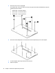
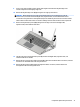
Remove the keyboard/top cover:
1. Close the computer.
2. Turn the computer upside down with the front toward you.
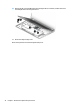
3. Remove the four computer feet (1).
4. Remove the two screw cover strips (2).
Component replacement procedures 29