HP EliteBook Folio 1040 G3 Notebook PC Maintenance and Service Guide
© Copyright 2016 HP Development Company, L.P. AMD is a trademark of Advanced Micro Devices, Inc. Bluetooth is a trademark owned by its proprietor and used by HP Inc. under license. Intel, Celeron, and Pentium are trademarks of Intel Corporation in the U.S. and other countries. Microsoft and Windows are trademarks of the Microsoft group of companies. The information contained herein is subject to change without notice.
Safety warning notice WARNING! To reduce the possibility of heat-related injuries or of overheating the device, do not place the device directly on your lap or obstruct the device air vents. Use the device only on a hard, flat surface. Do not allow another hard surface, such as an adjoining optional printer, or a soft surface, such as pillows or rugs or clothing, to block airflow. Also, do not allow the AC adapter to contact the skin or a soft surface, such as pillows or rugs or clothing, during operation.
iv Safety warning notice
Table of contents 1 Product description ....................................................................................................................................... 1 2 External component identification .................................................................................................................. 4 Display .................................................................................................................................................................... 4 Top ..
Battery ............................................................................................................................................... 29 RTC battery ........................................................................................................................................ 31 SSD drive ............................................................................................................................................ 32 WWAN module .......................................
Determining the BIOS version ......................................................................................... 67 Downloading a BIOS update ........................................................................................... 67 Changing the boot order using the f9 prompt .................................................................................. 68 TPM BIOS settings (select products only) ..................................................................................................
M.2 PCIe solid-state drive specifications ............................................................................................................ 90 13 Statement of memory volatility .................................................................................................................. 91 Nonvolatile memory usage ................................................................................................................................. 95 Questions and answers ..........................
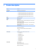
1 Product description Category Description Product Name HP EliteBook Folio 1040 G3 Notebook PC Processors 6th Generation Intel® Core® processors: ● i7-6600U 2.6-GHz (max turbo frequency 3.4-GHz), 4-MB L3 Cache, 15W ● i7-6500U 2.5-GHz (max turbo frequency 3.1-GHz), 4-MB L3 Cache, 15W ● i5-6300U 2.4-GHz (max turbo frequency 3.0-GHz), 3-MB L3 Cache, 15W ● i5-6200U 2.3-GHz (max turbo frequency 2.
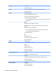
Category Description Microphone (dual array) Ethernet Intel I218LM Gigabit Network Connection (10/100/1000) with iAMT S3/S4/S5 wake on LAN Wireless WLAN options via M.2: Support "No WLAN/No Bluetooth" option Two WLAN antennas built into display assembly Support for the following WLAN format: ● Intel Dual Band Wireless-AC 8260 3rd Gen Intel 802.11ac, Dual Band, 2x2 Wi-Fi + Bluetooth 4.
Category Description 65-W HP Smart EM AC adapter 65-W Slim AC adapter Power cords: 2-wire plug (4.5 mm) (1.0 m) 3-wire plug with ground pin (4.5 mm) (1.0 m) 3-wire plug with ground pin (4.5 mm) (1.8 m) Battery: Supports a 6-cell, 45.6-Whr battery Security Security lock Fingerprint reader Supports Trusted Platform Module (TPM) 1.
2 External component identification Display Component Description (1) WWAN antennas (2)* (select products only) Send and receive wireless signals to communicate with wireless wide area networks (WWANs). (2) Internal microphones (2) Record sound. (3) Webcam light (select products only) On: The webcam is in use. (4) Webcam (select products only) Records video and captures photographs. Some models allow you to video conference and chat online using streaming video.
Component Description (6) Sends and receives wireless signals to communicate and transfer data/info to and from your NFC-compatible devices. Near Field Communication (NFC) antenna* (select products only) *The antennas are not visible from the outside of the computer. For optimal transmission, keep the areas immediately around the antennas free from obstructions. For wireless regulatory notices, see the section of the Regulatory, Safety, and Environmental Notices that applies to your country or region.
Top TouchPad Component 6 Description (1) TouchPad on/off button Turns the TouchPad on and off. (2) TouchPad zone Reads your finger gestures to move the pointer or activate items on the screen. (3) Left TouchPad button Functions like the left button on an external mouse. (4) Right TouchPad button Functions like the right button on an external mouse.
Lights Component (1) Description Power light ● On: The computer is on. ● Blinking: The computer is in the Sleep state, a power-saving state. The computer shuts off power to the display and other unneeded components. ● Off: The computer is off or in Hibernation. Hibernation is a power-saving state that uses the least amount of power. (2) Caps lock light On: Caps lock is on, which switches the key input to all capital letters. (3) Microphone mute light ● Amber: microphone sound is off.
Buttons, speakers, and fingerprint reader (select models only) Component (1) Description Power button ● When the computer is off, press the button to turn on the computer. ● When the computer is on, press the button briefly to initiate Sleep. ● When the computer is in the Sleep state, press the button briefly to exit Sleep. ● When the computer is in Hibernation, press the button briefly to exit Hibernation.
Component (3) Description Wireless button Turns the wireless feature on or off but does not establish a wireless connection. A wireless network must be set up before a wireless connection is possible. (4) Volume mute button Mutes and restores speaker sound. (5) Fingerprint reader Allows a fingerprint logon to Windows, instead of a password logon. Special function keys Component Description (1) esc key Displays system information when pressed in combination with the fn key.
Using the hot keys To use a hot key: ▲ Press the fn key, and then press the correct function key represented by the icons below. Press fn+function key Description Initiates Sleep, which saves your information in system memory. The display and other system components turn off and power is conserved. To exit Sleep, briefly press the power button. CAUTION: To reduce the risk of information loss, save your work before initiating Sleep. Turns the keyboard backlight off or on.
Left Component (1) Description Security cable slot Attaches an optional security cable to the computer. NOTE: The security cable is designed to act as a deterrent, but it may not prevent the computer from being mishandled or stolen. (2) Vent Enables airflow to cool internal components. NOTE: The computer fan starts up automatically to cool internal components and prevent overheating. It is normal for the internal fan to cycle on and off during routine operation. (3) USB 3.
Component Description NOTE: Be sure that the device cable has a 4-conductor connector that supports both audio-out (headphone) and audioin (microphone). (5) Smart card reader Supports optional Smart cards. Bottom Component Description (1) Docking device receptors (2) Connect an optional docking device. (2) Vents (2) Enable airflow to cool internal components. NOTE: The computer fan starts up automatically to cool internal components and prevent overheating.
Right Component (1) Description SIM slot plug (select products only) Supports a wireless subscriber identity module (SIM). NOTE: The SIM slot plug is removable on models that include HP Mobile Broadband. (2) USB Type-C (charging) port Connects any USB device with a Type-C connector. NOTE: USB Type-C ports charge products such as cell phones, laptops, tablets, and MP3 players, even when the computer is off.
Labels The labels affixed to the computer provide information you may need when you troubleshoot system problems or travel internationally with the computer. IMPORTANT: Check the following locations for the labels described in this section: the bottom of the computer, inside the battery bay, under the service door, or on the back of the display. ● Service label—Provides important information to identify your computer.
3 Illustrated parts catalog Computer major components Computer major components 15
Item Component Spare part number Display assembly (35.6-cm [14.0-inch], LED) The display is spared only as a full hinge-up. Individual subcomponents are not spared.
Item Component Spare part number ● Intel Core i7-6500U processor 844419-xxx ● Intel Core i5-6300U processor 844415-xxx ● Intel Core i5-6200U processor 844414-xxx (12) Audio board 844421-001 (13) Heat sink/thermal module with fans (includes replacement thermal material): 844425-001 (14) Solid-state drives (M.
Plastics/Rubber Kit Item Component Spare part number Plastics/Rubber Kit 844400-001 (1) Smart card insert (2) SIM card slot insert (3) Power button (4) Function button (5) Foam strip for use on WWAN modules Rubber insert for use in the WWAN socket (not illustrated) Rubber strip for use near the solid-state drive (not illustrated) 18 Chapter 3 Illustrated parts catalog
Cable Kit Item Component Spare part number Cable Kit 844396-001 (1) TouchPad cable (2) Function board cable (3) NFC cable Mass storage devices Description Spare part number Solid-State Drive (SATA III) 512-GB, TLC 848878-001 256-GB, SED, OPAL2, MLC 844406-001 256-GB, PCIe, MLC 844405-001 256-GB, TLC 844408-001 240-GB, TLC 844407-001 180-GB, MLC 844403-001 180-GB, SED, OPAL2, MLC 844404-001 128-GB, TLC 844402-001 Cable Kit 19
Miscellaneous parts Component Spare part number AC adapter: 45-W HP Smart AC adapter (non-PFC) – non-slim 741727-001 45-W AC adapter (non-PFC), 2-prong 742436-001 65-W HP Smart AC adapter, 4.5 mm, EM 714657-001 65-W HP Smart AC travel adapter 693716-001 NOTE: Use with cable 736697-001. 65-W HP Smart AC adapter (RC/V EM) for use in Asia, India, and the People’s Republic of China 693710-001 65-W HP Smart AC adapter 693711-001 Smart AC adapter dongle, 7.
Component Spare part number For use in Europe (Austria, Belgium, Finland, France, Germany, the Netherlands, Norway and Sweden) 213350-009 For use in India 404827-003 For use in Israel 398063-003 For use in Italy 213352-008 For use in Japan 349756-002 For use in North America 213349-009 For use in South Africa 361240-002 For use in South Korea 267836-008 For use in Switzerland 213354-008 For use in Taiwan 393313-003 For use in Thailand 285096-006 For use in the United Kingdom and Sing
22 Component Spare part number Essential Top Load Case 679921-001 HP Business Backpack 718548-001 Chapter 3 Illustrated parts catalog
4 Removal and replacement procedures preliminary requirements Tools required You will need the following tools to complete the removal and replacement procedures: ● Flat-bladed screw driver ● Torx T8 screw driver ● Phillips P0 and P1 screw drivers ● Non-marking pry tool Service considerations The following sections include some of the considerations that you must keep in mind during disassembly and assembly procedures.
Drive handling CAUTION: Drives are fragile components that must be handled with care. To prevent damage to the computer, damage to a drive, or loss of information, observe these precautions: Before removing or inserting a hard drive, shut down the computer. If you are unsure whether the computer is off or in Hibernation, turn the computer on, and then shut it down through the operating system. Before handling a drive, be sure that you are discharged of static electricity.
Typical electrostatic voltage levels Relative humidity Event 10% 40% 55% Walking across carpet 35,000 V 15,000 V 7,500 V Walking across vinyl floor 12,000 V 5,000 V 3,000 V Motions of bench worker 6,000 V 800 V 400 V Removing DIPS from plastic tube 2,000 V 700 V 400 V Removing DIPS from vinyl tray 11,500 V 4,000 V 2,000 V Removing DIPS from Styrofoam 14,500 V 5,000 V 3,500 V Removing bubble pack from PCB 26,500 V 20,000 V 7,000 V Packing PCBs in foam-lined box 21,000 V 11,0
Equipment guidelines Grounding equipment must include either a wrist strap or a foot strap at a grounded workstation. ● When seated, wear a wrist strap connected to a grounded system. Wrist straps are flexible straps with a minimum of one megohm ±10% resistance in the ground cords. To provide proper ground, wear a strap snugly against the skin at all times. On grounded mats with banana-plug connectors, use alligator clips to connect a wrist strap.
5 Removal and replacement procedures for Authorized Service Provider parts CAUTION: Components described in this chapter should only be accessed by an authorized service provider. Accessing these parts can damage the computer or void the warranty. Component replacement procedures NOTE: Details about your computer, including model, serial number, product key, and length of warranty, are on the service tag at the bottom of your computer. See Labels on page 14 for details.
Bottom cover Description Spare part number Bottom cover (includes feet) 844389-001 Before removing the bottom cover, follow these steps: 1. Turn off the computer. If you are unsure whether the computer is off or in Hibernation, turn the computer on, and then shut it down through the operating system. 2. Disconnect the power from the computer by unplugging the power cord from the computer. 3. Disconnect all external devices from the computer. 4. Remove the battery (see Battery on page 29).
Battery Description Spare part number 6-cell, 45-Wh, 2.0-Ah, Li ion battery (includes Mylar) 805096-005 Before disassembling the computer, follow these steps: 1. Turn off the computer. If you are unsure whether the computer is off or in Hibernation, turn the computer on, and then shut it down through the operating system. 2. Disconnect the power from the computer by unplugging the power cord from the computer. 3. Disconnect all external devices from the computer. 4.
3. Lift the battery out of the computer (2). NOTE: 30 In the locked position there will be no red color shown in the latch slot.
RTC battery Description Spare part number RTC battery (includes double-sided tape) 637193-001 Before removing the RTC battery, follow these steps: 1. Turn off the computer. If you are unsure whether the computer is off or in Hibernation, turn the computer on, and then shut it down through the operating system. 2. Disconnect the power from the computer by unplugging the power cord from the computer. 3. Disconnect all external devices from the computer. 4.
SSD drive Description Spare part number Solid-state drive 512-GB, TLC 848878-001 256-GB, SED, OPAL2, MLC 844406-001 256-GB, PCIe, MLC 844405-001 256-GB, TLC 844408-001 240-GB, TLC 844407-001 180-GB, MLC 844403-001 180-GB, SED, OPAL2, MLC 844404-001 128-GB, TLC 844402-001 Before removing the hard drive, follow these steps: 1. Turn off the computer. If you are unsure whether the computer is off or in Hibernation, turn the computer on, and then shut it down through the operating system. 2.
WWAN module NOTE: The WWAN module and the WLAN module are not interchangeable. NOTE: Models that do not have a WWAN module installed will have a rubber insert installed in the WWAN socket. Either a WWAN module or a rubber insert must be installed in the WWAN socket. The socket must never be empty. The rubber insert is included in the Plastics/Rubber Kit, spare part number 844400-001.
3. Disconnect the WWAN antenna cables (2) from the terminals on the WWAN module. NOTE: The red WWAN antenna cable is connected to the WWAN module “Main” terminal. The blue WWAN antenna cable is connected to the WWAN module “Aux” terminal. 4. Remove the Phillips PM2.0×3.0 screw (3) that secures the WWAN module to the system board. 5. Remove the WWAN module (4) by pulling the module away from the slot. NOTE: WWAN modules are designed with a notch to prevent incorrect insertion.
Component replacement procedures 35
WLAN module Description Spare part number Intel Dual Band Wireless-AC 8260 802.11ac 2×2 WiFi + Bluetooth 4.2 806721-005 CAUTION: To prevent an unresponsive system, replace the wireless module only with a wireless module authorized for use in the computer by the governmental agency that regulates wireless devices in your country or region. If you replace the module and then receive a warning message, remove the module to restore device functionality, and then contact technical support.
3. Remove the WLAN module (3) by pulling the module away from the slot at an angle. NOTE: WLAN modules are designed with a notch to prevent incorrect insertion. NOTE: If the WLAN antennas are not connected to the terminals on the WLAN module, the protective sleeves must be installed on the antenna connectors, as shown in the following illustration. Reverse this procedure to install the WLAN module.
Power connector Description Spare part number Power connector 844424-001 Before removing the power connector, follow these steps: 1. Turn off the computer. If you are unsure whether the computer is off or in Hibernation, turn the computer on, and then shut it down through the operating system. 2. Disconnect the power from the computer by unplugging the power cord from the computer. 3. Disconnect all external devices from the computer. 4. Remove the bottom cover (see Bottom cover on page 28). 5.
Display assembly Description Spare part number Touch screen displays: ● Without WWAN and with webcam 844386-001 ● With WWAN and with webcam 849783-001 Non-touch screen displays: ● FHD, SVA 846579-001 ● QHD, UWVA 846580-001 ● FHD, SVA, with WWAN 849777-001 ● FHD, SVA, with webcam 849778-001 ● FHD, SVA, with WWAN and webcam 849779-001 ● QHD, UWVA, with WWAN 849780-001 ● QHD, UWVA, with webcam 849781-001 ● QHD, UWVA, with WWAN and webcam 849782-001 NOTE: The display is spared o
5. Remove the touch cable from the right fan, and then disconnect the cable from the system board (4). 6. Remove the four Phillips PM2.0×4.0 screws (1) that secure the display assembly to the computer. 7. Open the display up to a 45 degree angle and position it with the base enclosure on a table and the display hanging down (2). 8. Remove the computer from the display assembly (3). Reverse this procedure to reassemble and install the display assembly.
Keyboard In this section, the first table provides the main spare part number for the keyboard. The second table provides the country codes.
42 2. Remove the two Phillips PM2.0×3.0 screws (3) that secure the keyboard to the computer. 3. Position the computer so you can access the bottom while the keyboard is free to be disengaged. 4. Insert a screwdriver or similar thin tool into the keyboard release opening, and then press on the back of the keyboard until the keyboard disengages from the computer (1). 5. Rotate the keyboard off the top cover (2). 6. Position the computer upright and open as far as possible.
7. Pry around the edges of the keyboard to disengage it (1), and the lift the keyboard off the computer (2). Reverse this procedure to install the keyboard. When you install the keyboard, you have to insert the cables through the slots in the top cover (under the keyboard).
TouchPad Description Spare part number TouchPad 844394-001 NOTE: The TouchPad cable is available in the Cable Kit, spare part number 844396-001. The NFC antenna is available using spare part number 857632-001. Before removing the TouchPad, follow these steps: 1. Turn off the computer. If you are unsure whether the computer is off or in Hibernation, turn the computer on, and then shut it down through the operating system. 2.
NFC module Description Spare part number NFC (Near Field Communication) module 844392-001 Before removing the NFC module, follow these steps: 1. Turn off the computer. If you are unsure whether the computer is off or in Hibernation, turn the computer on, and then shut it down through the operating system. 2. Disconnect the power from the computer by unplugging the power cord from the computer. 3. Disconnect all external devices from the computer. 4.
Heat sink/fan assembly NOTE: The heat sink/fan assembly spare part kit includes replacement thermal material. Description Spare part number Heat sink/thermal module with fans 844425-001 Before removing the heat sink/fan assembly, follow these steps: 1. Turn off the computer. If you are unsure whether the computer is off or in Hibernation, turn the computer on, and then shut it down through the operating system. 2.
4. Using both hands, lift up both fans at the same time and remove the assembly (4). CAUTION: Take extreme care when removing the heat sink and fan assembly. The heatpipes between the fans are very fragile and can be easily damaged and bent during removal. NOTE: The thermal material must be thoroughly cleaned from the surfaces of the heat sink and the system board components each time the heat sink is removed.
System board NOTE: The system board spare part kit includes replacement thermal material.
2.
50 ● (4): Right fan ● (5): NFC module ● (6): Audio board 3. Remove the seven Phillips PM2.0×4.0 screws (1) that secure the system board to the computer. 4. Remove the four Phillips PM2.0×4.0 screws (2) that secure the fans to the computer.
5. Remove the two Phillips PM2.0×3.0 screws (3) that secure the keyboard to the computer. Lift the left side of the system board up to an approximate 45 degree angle (1). Pull the system board to the left to remove it from the computer (2). Reverse this procedure to install the system board.
Updating DMI After replacing a system board in an HP EliteBook product, you must configure and customize the replacement system board with notebook-specific information, such as the serial number, product name, and number. The information is programmed to the Electrically Erasable Programmable Read-Only Memory (EEPROM) of the system board. The DMI update process usually involves the following procedures: 1.
Required information The following table summarizes the required DMI information entered during the flashing process. Location Information Description Service label Serial number The customer system's serial number. SKU number (Product Number) The customer system's SKU (stock-keeping unit) number. Notebook Model (Product Name) The customer system's model name. CTO localization (commercial only) The CTO localization defines the language and other regional features.
Smart Card reader Description Spare part number Smart Card reader (includes cable) 844412-001 NOTE: The Smart Card reader insert is included in the Plastics/Rubber Kit, spare part number 844400-001. Before removing the Smart Card reader, follow these steps: 1. Turn off the computer. If you are unsure whether the computer is off or in Hibernation, turn the computer on, and then shut it down through the operating system. 2.
Light pipe Before removing the light pipe, follow these steps: 1. Turn off the computer. If you are unsure whether the computer is off or in Hibernation, turn the computer on, and then shut it down through the operating system. 2. Disconnect the power from the computer by unplugging the power cord from the computer. 3. Disconnect all external devices from the computer. 4. Remove the bottom cover (see Bottom cover on page 28) 5. Remove the battery (see Battery on page 29). 6.
Buttons (power, function) NOTE: The power button and function button are included in the Plastics/Rubber Kit, spare part number 844400-001. Description Spare part number Plastics/Rubber Kit 844400-001 Before removing the power button and function button, follow these steps: 1. Turn off the computer. If you are unsure whether the computer is off or in Hibernation, turn the computer on, and then shut it down through the operating system. 2.
Multi-function board Description Spare part number Function board 844420-001 Before removing the function board, follow these steps: 1. Turn off the computer. If you are unsure whether the computer is off or in Hibernation, turn the computer on, and then shut it down through the operating system. 2. Disconnect the power from the computer by unplugging the power cord from the computer. 3. Disconnect all external devices from the computer. 4.
Audio board Description Spare part number Audio board 844421-001 Before removing the audio board, follow these steps: 1. Turn off the computer. If you are unsure whether the computer is off or in Hibernation, turn the computer on, and then shut it down through the operating system. 2. Disconnect the power from the computer by unplugging the power cord from the computer. 3. Disconnect all external devices from the computer. 4. Remove the bottom cover (see Bottom cover on page 28) 5.
Fingerprint reader board Description Spare part number Fingerprint reader board (includes cable) 844410-001 NOTE: The fingerprint reader bracket is included in the Bracket Kit, spare part number 844411-001. Before removing the fingerprint reader board, follow these steps: 1. Turn off the computer. If you are unsure whether the computer is off or in Hibernation, turn the computer on, and then shut it down through the operating system. 2.
Speaker assembly Description Spare part number Speaker assembly (includes cable) 844409-001 Before removing the speaker assembly, follow these steps: 1. Turn off the computer. If you are unsure whether the computer is off or in Hibernation, turn the computer on, and then shut it down through the operating system. 2. Disconnect the power from the computer by unplugging the power cord from the computer. 3. Disconnect all external devices from the computer. 4.
6 Computer Setup (BIOS), TPM, and HP Sure Start in Windows 7 Using Computer Setup Computer Setup, or Basic Input/Output System (BIOS), controls communication between all the input and output devices on the system (such as disk drives, display, keyboard, mouse, and printer). Computer Setup includes settings for the types of devices installed, the startup sequence of the computer, and the amount of system and extended memory. NOTE: Use extreme care when making changes in Computer Setup.
To exit Computer Setup menus, choose one of the following methods: ● To exit Computer Setup menus without saving your changes: Select the Exit icon in the lower-right corner of the screen, and then follow the on-screen instructions. – or – Select Main, select Ignore Changes and Exit, and then press enter. ● To save your changes and exit Computer Setup menus: Select the Save icon in the lower-right corner of the screen, and then follow the on-screen instructions.
1. Start Computer Setup. See Starting Computer Setup on page 61. 2. Select Main, and then select System Information. 3. To exit Computer Setup without saving your changes, select the Exit icon in the lower-right corner of the screen, and then follow the on-screen instructions. – or – Select Main, select Ignore Changes and Exit, and then press enter. To check for later BIOS versions, see Downloading a BIOS update on page 63.
NOTE: After a message on the screen reports a successful installation, you can delete the downloaded file from your hard drive. Changing the boot order using the f9 prompt To dynamically choose a boot device for the current startup sequence, follow these steps: 1. Access the Boot Device Options menu: ● Computers or tablets with keyboards: ▲ ● Tablets without keyboards: ▲ 2. Turn on or restart the computer, and when the HP logo appears, press f9 to enter the Boot Device Options menu.
7 Computer Setup (BIOS), TPM, and HP Sure Start in Windows 10 Using Computer Setup Computer Setup, or Basic Input/Output System (BIOS), controls communication between all the input and output devices on the system (such as disk drives, display, keyboard, mouse, and printer). Computer Setup includes settings for the types of devices installed, the startup sequence of the computer, and the amount of system and extended memory. NOTE: Use extreme care when making changes in Computer Setup.
To exit Computer Setup menus, choose one of the following methods: ● To exit Computer Setup menus without saving your changes: Select the Exit icon in the lower-right corner of the screen, and then follow the on-screen instructions. – or – Select Main, select Ignore Changes and Exit, and then press enter. ● To save your changes and exit Computer Setup menus: Select the Save icon in the lower-right corner of the screen, and then follow the on-screen instructions.
Updating the BIOS Updated versions of the BIOS may be available on the HP website. Most BIOS updates on the HP website are packaged in compressed files called SoftPaqs. Some download packages contain a file named Readme.txt, which contains information regarding installing and troubleshooting the file. Determining the BIOS version To decide whether you need to update Computer Setup (BIOS), first determine the BIOS version on your computer.
NOTE: If you connect your computer to a network, consult the network administrator before installing any software updates, especially system BIOS updates. BIOS installation procedures vary. Follow any instructions that are revealed on the screen after the download is complete. If no instructions are revealed, follow these steps: 1. Type file in the taskbar search box, and then select File Explorer. 2. Select your hard drive designation. The hard drive designation is typically Local Disk (C:). 3.
Using HP Sure Start (select products only) Select computer models are configured with HP Sure Start, a technology that continuously monitors the computer's BIOS for attacks or corruption. If the BIOS becomes corrupted or is attacked, HP Sure Start automatically restores the BIOS to its previously safe state, without user intervention. HP Sure Start is configured and already enabled so that most users can use the HP Sure Start default configuration.
8 DMI programming procedures HP Commercial Notebooks that use the HP Common Core BIOS no longer require the WNDIFIT tool to update DMI information. Instead, the DMI information can be entered directly into the HP Computer Setup utility when the notebook is in MPM Unlock mode. HP Common Core BIOS Programming Process After system board replacement, the BIOS should be in Manufacturer’s Programming Mode (MPM), and ‘Panic Mode’.
Programming steps This is the process for the HP Common Core BIOS. WARNING! Completing the DMI programming process allows you to lock the system at the conclusion preventing further programming. A system-specific MPM unlock key is required to reprogram the system after it has been locked. 1. Start the computer. The computer should be in MPM mode and ready for DMI Programming. NOTE: If the computer is not in MPM mode, you will be unable to program it and you must obtain a SMC.BIN file to unlock the system.
IMPORTANT: The system clock must be set correctly to generate a valid UUID. ● To set the system clock in Windows, right-click the clock on the bottom right corner of the screen and select Adjust date/time. ● To set the system clock using an EFI-bootable shell: Create a bootable EFI Shell DOK: ◦ On a FAT32-formatted DOK and create a directory called EFI\boot\ ◦ Copy shellfull.efi to it. (See http://tianocore.sourceforge.net/wiki/Efi-shell) ◦ Rename shellfull.efi to bootx64.efi.
6. Program each field: 7. When complete, select Main > Save Changes and Exit. 8. After populating all DMI fields, you are prompted to confirm the data and lock the MPM. Click Confirm. Click Cancel to skip locking the system and boot to the operating system. NOTE: The confirmation screen displays on each boot until the system is locked. 9. Press the enter key to exit the BIOS and restart the computer. Confirm that the system is not in MPM mode.
9 Using HP PC Hardware Diagnostics (UEFI) HP PC Hardware Diagnostics is a Unified Extensible Firmware Interface (UEFI) that allows you to run diagnostic tests to determine whether the computer hardware is functioning properly. The tool runs outside the operating system so that it can isolate hardware failures from issues that are caused by the operating system or other software components.
3. Use the categories listed to find your product. – or – Click Find Now to let HP automatically detect your product. 4. Select your computer, and then select your operating system. 5. In the Diagnostic section, follow the on-screen instructions to select and download the UEFI version you want.
10 Backup and recovery in Windows 7 Your computer includes HP and Windows tools to help you safeguard your information and retrieve it if you ever need to. These tools will help you return your computer to a proper working state, all with simple steps. This section provides information about the following processes: ● Creating recovery media and backups ● Restoring and recovering your system Creating recovery media and backups Recovery after a system failure is only as good as your most recent backup.
applications if the hard drive becomes corrupted. HP Recovery Disc Creator can create two kinds of recovery DVDs: ● Windows 7 operating system DVD—Installs the operating system without additional drivers or applications. ● Driver Recovery DVD—Installs specific drivers and applications only, in the same way that the HP Software Setup utility installs drivers and applications. Creating recovery media NOTE: The Windows 7 operating system DVD can be created only once.
To create a backup using Windows Backup and Restore: NOTE: The backup process may take over an hour, depending on file size and the speed of the computer. 1. Select Start > All Programs > Maintenance > Backup and Restore. 2. Follow the on-screen instructions to set up your backup, create a system image (select products only), or create system repair media (select products only).
1. If possible, back up all personal files. 2. If possible, check for the presence of the Windows partition. To check for the Windows partition, select Start > Computer. NOTE: If the Windows partition is not listed, you must recover your operating system and programs using the Windows 7 operating system DVD and the Driver Recovery media. For additional information, see Using Windows 7 operating system media on page 79. 3.
NOTE: This process takes several minutes. 1. If possible, back up all personal files. 2. Restart the computer, and then insert the Windows 7 operating system DVD into the optical drive before the Windows operating system loads. 3. When prompted, press any keyboard key. 4. Follow the on-screen instructions. 5. Click Next. 6. Select Repair your computer. 7. Follow the on-screen instructions. After the repair is completed: 80 1.
11 Backup and recovery in Windows 10 This chapter provides information about the following processes. The information in the chapter is standard procedure for most products. ● Creating recovery media and backups ● Restoring and recovering your system For additional information, refer to the HP support assistant app. ▲ Type support in the taskbar search box, and then select the HP Support Assistant app. ‒ or – Click the question mark icon in the taskbar.
You can use Windows tools to create system restore points and create backups of personal information, see Using Windows tools on page 82. ● If your computer does list the Recovery partition and the Windows partition, you can use HP Recovery Manager to create recovery media after you successfully set up the computer. HP Recovery media can be used to perform system recovery if the hard drive becomes corrupted.
Restore and recovery There are several options for recovering your system. Choose the method that best matches your situation and level of expertise: IMPORTANT: ● Windows offers several options for restoring from backup, refreshing the computer, and resetting the computer to its original state. For more information see the Get started app. ▲ ● Not all methods are available on all products. Select the Start button, and then select the Get started app.
website. Go to http://www.hp.com/support, select your country or region, and follow the on-screen instructions. IMPORTANT: HP Recovery Manager does not automatically provide backups of your personal data. Before beginning recovery, back up any personal data you want to retain. Using HP Recovery media, you can choose from one of the following recovery options: NOTE: Only the options available for your computer display when you start the recovery process.
Changing the computer boot order If your computer does not restart in HP Recovery Manager, you can change the computer boot order, which is the order of devices listed in BIOS where the computer looks for startup information. You can change the selection to an optical drive or a USB flash drive. To change the boot order: IMPORTANT: For a tablet with a detachable keyboard, connect the keyboard to the keyboard dock before beginning these steps. 1. Insert the HP Recovery media. 2.
Removing the HP Recovery partition (select products only) HP Recovery Manager software allows you to remove the HP Recovery partition to free up hard drive space. IMPORTANT: After you remove the HP Recovery partition, you will not be able to perform System Recovery or create HP recovery media from the HP Recovery partition. So before you remove the Recovery partition, create HP Recovery media; see Creating HP Recovery media (select products only) on page 81.
12 Specifications Computer specifications Metric U.S. Width 33.70 cm 13.27 in Depth 23.5 cm 9.23 in Height (non-touch) 1.58 cm 0.62 in Height (touch) 1.65 cm 0.65 in Non-touch 1.43 kg 3.15 lbs Touch 1.54 kg 3.4 lbs Dimensions Weight (weight varies based on configuration) Input power Operating voltage and current 18.5 V dc @ 3.5 A - 65 W – or – 19.0 V dc @ 4.
35.6-cm (14.0-in) display specifications Metric U.S. Height 17.6 cm 6.93 in Width 31.2 cm 12.28 in Diagonal 35.7 cm 14.
M.2 solid-state drive specifications 128-GB* 180-GB* 240-GB* 256-GB* 512-GB* Height 1 mm 1 mm 1 mm 1 mm 1 mm Length 50.8 mm 50.8 mm 50.8 mm 50.8 mm 50.8 mm Width 28.9 mm 28.9 mm 28.9 mm 28.9 mm 28.
M.2 PCIe solid-state drive specifications 256-GB* Dimensions Height 1 mm Length 50.8 mm Width 28.9 mm Weight < 10 g Interface type ATA-7 Transfer rate Sequential Read Up to 2150 MB/s Random Read Up to 300.,000 IOPs Sequential Write Up to 1260 MB/s Random Write Up to 100,000 IOPs Ready time, Maximum (to not busy) 1.0 s Access times Logical 0.
13 Statement of memory volatility The purpose of this chapter is to provide general information regarding nonvolatile memory in HP Business PCs. This chapter also provides general instructions for restoring nonvolatile memory that can contain personal data after the system has been powered off and the hard drive has been removed. HP Business PC products that use Intel®-based or AMD®-based system boards contain volatile DDR memory.
g. If a DriveLock password is set, select the Security menu, and scroll down to Hard Drive Utilities under the Utilities menu. Select Hard Drive Utilities, select DriveLock, then uncheck the checkbox for DriveLock password on restart. Select OK to proceed. h. Select the Main menu, and then select Reset BIOS Security to factory default. Click Yes at the warning message. The computer will reboot. i.
NOTE: If the system has a BIOS administrator password, enter the password at the prompt. 2. a. Select Main, select Restore Defaults, and then select Yes to load defaults. b. Select the Security menu, select Restore Security Level Defaults, and then select Yes to restore security level defaults. c. If an asset or ownership tag is set, select the Security menu and scroll down to the Utilities menu. Select System IDs, and then select Asset Tracking Number.
NOTE: The amount of time it takes for Disk Sanitizer to run can take several hours. Plug the computer into an AC outlet before starting. 94 a. Turn on or restart the computer, and then press esc while the "Press the ESC key for Startup Menu" message is displayed at the bottom of the screen. b. Select the Security menu and scroll down to the Utilities menu. c. Select Hard Drive Tools. d.
Nonvolatile memory usage Nonvolatile Memory Type Amount (Size) Does this memory store customer data? Does this memory retain data when power is removed? What is the purpose of this memory? How is data input into this memory? How is this memory write-protected? HP Sure Start flash (select models only) 2 MBytes No Yes Provides protected backup of critical System BIOS code, EC firmware, and critical PC configuration data for select platforms that support HP Sure Start.
Nonvolatile Memory Type Amount (Size) Does this memory store customer data? Does this memory retain data when power is removed? What is the purpose of this memory? How is data input into this memory? How is this memory write-protected? Downloads, and then follow the on-screen instructions. 96 Intel Management 1.5 MBytes or 5 Engine Firmware MBytes (present in only specific ZBook and EliteBook models. For more information, go to http://www.hp.com/ support, and select your country.
Questions and answers 1. How can the BIOS settings be restored (returned to factory settings)? IMPORTANT: Restore defaults does not securely erase any data on your hard drive. See question and answer 6 for steps to securely erase data. Restore defaults does not reset the Custom Secure Boot keys. See question and answer 7 for information about resetting the keys. 2. a.
IMPORTANT: Resetting will result in the loss of information. These steps will not reset Custom Secure Boot Keys. See question and answer 7 for information about resetting the keys. 7. a. Turn on or restart the computer, and then press esc while the "Press the ESC key for Startup Menu" message is displayed at the bottom of the screen. b. Select Main, and then select Reset BIOS Security to Factory Default. c. Follow the on-screen instructions. d.
14 Power cord set requirements The wide-range input feature of the computer permits it to operate from any line voltage from 100 to 120 volts AC, or from 220 to 240 volts AC. The 3-conductor power cord set included with the computer meets the requirements for use in the country or region where the equipment is purchased. Power cord sets for use in other countries and regions must meet the requirements of the country or region where the computer is used.
Country/region Accredited agency Applicable note number Sweden SEMKO 1 Switzerland SEV 1 Taiwan BSMI 4 The United Kingdom BSI 1 The United States UL 2 1. The flexible cord must be Type HO5VV-F, 3-conductor, 1.0-mm² conductor size. Power cord set fittings (appliance coupler and wall plug) must bear the certification mark of the agency responsible for evaluation in the country or region where it will be used. 2. The flexible cord must be Type SPT-3 or equivalent, No. 18 AWG, 3-conductor.
15 Recycling When a non-rechargeable or rechargeable battery has reached the end of its useful life, do not dispose of the battery in general household waste. Follow the local laws and regulations in your area for battery disposal. HP encourages customers to recycle used electronic hardware, HP original print cartridges, and rechargeable batteries. For more information about recycling programs, see the HP Web site at http://www.hp.com/recycle.
Index A AC adapter, spare part numbers 20 audio board removal 17, 58 spare part number 58 audio, product description 1 audio-out (headphone)/audio-in (microphone) combo jack, identifying 11 B Backup and Restore 78 backup tools 76 backups 81 creating 77 recovering 78 battery removal 29 spare part number 17 spare part numbers 29 battery light 13 BIOS determining version 62, 67 downloading an update 63, 67 updating 62, 67 Blu-ray R/RE DVD±RW SuperMulti DL Drive precautions 24 Blu-ray ROM DVD±RW SuperMulti DL D
HP PC Hardware Diagnostics (UEFI) using 74 HP Recovery Disc Creator, using 76 HP Recovery Manager correcting boot problems 85 starting 84 HP Recovery media creating 81 recovery 84 HP Recovery partition checking for presence 79 recovery 84 removing 86 using for recovery 79 HP Sure Start 98 I integrated webcam light, identifying 4 internal microphones, identifying 4 J jacks audio-out (headphone)/audio-in (microphone) combo 11 K keyboard product description 2 remval 41 spare part numbers 16, 41 keypad embedd
power requirements 2 primary storage 1 processors 1 product name 1 security 3 serviceability 3 video 1 wireless 2 product name 1 product name and number, computer 14 R recover options 83 recovery discs 82, 84 HP Recovery Manager 83 media 84 starting 84 supported discs 82 system 83 USB flash drive 84 using HP Recovery media 82 recovery media creating 81 creating using HP Recovery Manager 82 recovery media, creating 76 recovery media, using for restore 79 recovery partition 79 removing 86 recovery tools 76 re
Windows tools using 82 wireless antennas, identifying 4 wireless certification label 14 wireless light 7 wireless, product description 2 WLAN antennas, identifying 4 WLAN device 14 WLAN label 14 WLAN module removal 36 spare part numbers 17, 36 workstation guidelines 25 WWAN antennas, identifying 4 WWAN module removal 33 spare part numbers 17, 33 Index 105