Hardware Reference Guide HP Thin Clients
© Copyright 2014 Hewlett-Packard Development Company, L.P. The information contained herein is subject to change without notice. The only warranties for HP products and services are set forth in the express warranty statements accompanying such products and services. Nothing herein should be construed as constituting an additional warranty. HP shall not be liable for technical or editorial errors or omissions contained herein. This document contains proprietary information that is protected by copyright.
About This Book WARNING! Text set off in this manner indicates that failure to follow directions could result in bodily harm or loss of life. CAUTION: Text set off in this manner indicates that failure to follow directions could result in damage to equipment or loss of information. NOTE: Text set off in this manner provides important supplemental information.
iv About This Book
Table of contents 1 Product features ................................................................................................................................................ 1 Standard features ................................................................................................................................. 1 Front panel components ....................................................................................................................... 2 Rear panel components ..........
Supported orientations ....................................................................................................................... 24 Non-supported orientations ................................................................................................................ 25 Appendix D Electrostatic discharge ................................................................................................................... 26 Preventing electrostatic damage .....................................
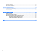
1 Product features Standard features Thank you for purchasing an HP thin client. We hope you have years of use from our thin clients. Our goal is to provide you with award-winning clients that are easy to deploy and manage with the power and reliability you expect. The next sections describe the features of the thin client. For a complete list of the hardware and software installed on a specific model, visit http://www.hp.com and search for your specific thin client model.
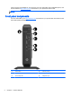
Various options are available for your thin client. For more information about available options, visit the HP website at http://www.hp.com and search for your specific thin client model. NOTE: Your thin client model may look different than the model in the following illustrations. Front panel components For more information, go to http://www.hp.com and search for your specific thin client model to find the model-specific QuickSpecs. 2 (1) Power button (4) USB 3.
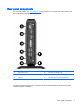
Rear panel components For more information, go to http://www.hp.com and search for your specific thin client model to find the model-specific QuickSpecs. (1) Ethernet RJ-45 port (5) External power adapter input (2) Dual-mode DisplayPort 1.2 ports (2) (6) Cable lock slot (3) VGA port (7) HP USB Legacy Port Module retention slot (4) USB 2.
● If a VGA device is connected at boot up, then only one DisplayPort port may be used. If the VGA device is subsequently disconnected, then both DisplayPort ports are enabled. ● If a VGA device and one DisplayPort device are connected at boot up, then the other DisplayPort port is disabled. If the VGA device is subsequently disconnected, then that DisplayPort port is enabled. ● If two DisplayPort devices are connected at boot up, then the VGA port is disabled.
2 Hardware changes Warnings and cautions Before performing upgrades be sure to carefully read all of the applicable instructions, cautions, and warnings in this guide. WARNING! To reduce the risk of personal injury or equipment damage from electric shock, hot surfaces, or fire: Disconnect the power cord from the power outlet and allow the internal system components to cool before you touch them. Do not plug telecommunications or telephone connectors into the network interface controller (NIC) receptacles.
Connecting the power cord 1. Plug the female end of the power cord into the power supply brick (1). 2. Connect the other end of the power cord to an electrical outlet (2). 3. Connect the round end of the power supply cord to the power supply connector on the rear of the thin client (3). 4. Press the power cord into the retention hook (4) and bundle any excess power cord.
Attaching the stand CAUTION: Unless the thin client is mounted with the HP Quick Release, it must be operated with the stand attached to ensure proper airflow around the thin client. Adjusting the stand The stand can be adjusted into two configurations: square for the horizontal position and rectangular for the vertical position. Take the stand apart by removing the two short pieces connecting the two sides.
● 8 a. Turn the thin client upside down and locate the two screw holes in the grid on the bottom of the thin client. b. Position the stand (1) over the bottom of the thin client and line up the captive screws in the stand with the screw holes in the thin client. c. Tighten the captive screws (2) securely. Attach the stand to the right side of the thin client to use it in the horizontal orientation. a.
7. Reconnect the external equipment, plug the power cord into a power outlet, and then turn the thin client on. NOTE: Be sure that at least 10.2 centimeters (4 inches) of space on all sides of the thin client remain clear and free of obstructions. NOTE: An optional Quick Release mounting bracket is available from HP for mounting the thin client to a wall, desk, or swing arm. When the mounting bracket is used, do not install the thin client with the I/O ports oriented towards the ground.
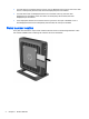
10 5. Remove the thin client from the stand. 6. Lay the unit flat on a stable surface with the right side up. 7. Remove the two screws from the back I/O panel (1). 8. Slide the access panel approximately 6 mm (.24 in) toward the back of the chassis, and then lift the panel off of the thin client (2).
Replacing the access panel To replace the access panel: 1. Align the three tabs on each side of the access panel with the slots in the chassis. Set the access panel on the chassis, approximately 6 mm (.24 in) inside the edge of the chassis, and then slide the panel toward the front of the chassis (1) into place. 2. Fasten the two screws into the ends of the back I/O panel to secure the access panel (2).
Populating the SODIMM socket There is one SODIMM socket on the system board. The socket is labeled DIMM1. Installing SODIMM CAUTION: You must disconnect the power cord and wait approximately 30 seconds for the power to drain before adding or removing the memory module. Regardless of the power-on state, voltage is always supplied to the memory module as long as the thin client is plugged into an active AC outlet.
7. Locate the memory compartment on the system board. 8. To remove the SODIMM, press outward on the two latches (1) on each side of the SODIMM. 9. Rotate the SODIMM up, and then pull the SODIMM out of the socket (2).
10. Slide the new SODIMM (1) into the socket at approximately a 30° angle, and then press the SODIMM into the socket (2) so that the latches lock it in place. NOTE: A memory module can be installed in only one way. Match the notch on the module with the tab on the memory socket. 11. Replace and secure the access panel. See Removing and replacing the access panel on page 9. 12. Replace the thin client stand. 13. Reconnect the power cord and turn on the thin client. 14.
Security These thin clients are designed to accept a security cable lock. The cable lock prevents unauthorized removal of the thin client. You may also purchase a port cover to help secure the rear ports. To order either option, visit the HP website at http://www.hp.com and search for your specific thin client model. Cable lock 1. Locate the cable lock slot on the back panel. 2. Insert the cable lock into the slot, and then use the key to lock it.
Mounting the thin client HP recommends mounting the thin client in the vertical (tower) orientation, with the HP logo right-side up. Mounting in other orientations may result in decreased performance under certain conditions; operating the thin client with limited power to prevent overheating is one such condition. This thin client incorporates four mounting points on the right side of the unit.
3. Using four screws included in the mounting device kit, attach the other side of the HP Quick Release to the device to which you will mount the thin client. Make sure the release lever points upward. 4. Slide the side of the mounting device attached to the thin client (1) over the other side of the mounting device (2) on the device on which you want to mount the thin client. An audible 'click' indicates a secure connection. When attached, the HP Quick Release automatically locks in position.
Supported mounting options The following illustrations demonstrate some of the supported mounting options for the mounting bracket.
A Specifications For the latest specifications or additional specifications on the thin client, go to http://www.hp.com/go/ quickspecs/ and search for your specific model to find the model-specific QuickSpecs. Dimensions Width 45.1 mm 1.78 in. Depth 200 mm 7.87 in Height (without stand) 200.1 mm 7.88 In Height (with stand) 210.5 mm 8.29 in. Approximate Weight 1,037.1 g 36.59 oz 10°C to 40°C 50°F to 104°F -30°C to 60°C -22°F to 140°F Temperature Range (fanless design)* Operating** (max.
Power Supply Operating Voltage Range Rated Line Frequency 20 100 VAC to 240 VAC 50 Hz to 60 Hz Power Output (maximum) 65 W Rated Output Current (maximum) 3.33 A Output Voltage +19.
B Removing and replacing the battery WARNING! Before removing the access panel, be sure that the thin client is turned off and the power cord is disconnected from the electrical outlet. To remove and replace the battery: 1. Remove/disengage any security devices that prohibit opening the thin client. 2. Remove all removable media, such as USB flash drives, from the thin client. 3. Turn off the thin client properly through the operating system, and then turn off any external devices. 4.
9. To insert the new battery, slide one edge of the replacement battery under the holder’s lip with the positive side up. Push the other edge down until the clamp snaps over the other edge of the battery (2). 10. Replace and secure the access panel. See Removing and replacing the access panel on page 9. 11. Replace the thin client stand. 12. Reconnect the power cord and turn on the thin client. 13. Lock any security devices that were disengaged when the thin client cover or access panel was removed.
C Thin client operation Routine thin client care Use the following information to properly care for your thin client: ● Never operate the thin client with the outside panel removed. ● Keep the thin client away from excessive moisture, direct sunlight, and extreme heat and cold. For information about the recommended temperature and humidity ranges for the thin client, see Specifications on page 19. ● Keep liquids away from the thin client and keyboard.
Supported orientations HP supports the following orientations for the thin client.
Non-supported orientations HP does not support the following orientations for the thin client. CAUTION: Non-supported placement of thin clients could result in operation failure and/or damage to the devices. CAUTION: the vents. Thin clients require proper ventilation to maintain operating temperature. Do not block Do not put thin clients in drawers or other sealed enclosures. Do not place a monitor or other object on top of the thin client.
D Electrostatic discharge A discharge of static electricity from a finger or other conductor may damage system boards or other static-sensitive devices. This type of damage may reduce the life expectancy of the device. Preventing electrostatic damage To prevent electrostatic damage, observe the following precautions: ● Avoid hand contact by transporting and storing products in static-safe containers.
E Shipping information Shipping preparation Follow these suggestions when preparing to ship the thin client: 1. Turn off the thin client and external devices. 2. Disconnect the power cord from the electrical outlet, and then from the thin client. 3. Disconnect the system components and external devices from their power sources, and then from the thin client. 4.
Removing and replacing the solid state drive (flash memory) Removing the solid state drive (flash memory) The solid state drive should be removed before returning the thin client to HP for repair or exchange. To remove the solid state drive (SSD), perform the following steps: 1. Remove/disengage any security devices that prohibit opening the thin client. 2. Remove all removable media, such as USB flash drives, from the thin client. 3.
8. Use a Torx 8 screwdriver to unscrew the post securing the SSD to the system board. 9. Carefully pull the SSD out of the socket. Store the SSD carefully until it can be installed in the returned thin client. 10. Replace and secure the access panel. See Removing and replacing the access panel on page 9. Installing the solid state drive (flash memory) To Install the solid state drive (SSD), perform the following steps: 1. Position the post in the notch in the SSD.
2. 30 Hold the post in place and slide the SSD into the socket.
3. Use a Torx 8 screwdriver to fasten the screw and secure the SSD to the system board.
Index A access panel removing 9 replacing 11 altitude specifications 19 B battery, replacing 21 C cable lock 15 cable lock slot 3 cautions attaching the stand 7 electric shock 5, 9, 12 HP Quick Release 17 installing SODIMM 12 removing the battery 21 securing the power cable 6 static electricity 5 thin client orientation 25 ventilation 25 components front panel 2 rear panel 3 D dimensions 19 dual-mode DisplayPort 1.
specifications altitude 19 dimensions 19 hardware 19 humidity 19 power output 20 power supply 20 rated output current 20 relative humidity 19 temperature 19 thin client 19 specifications, memory 11 SSD installing 29 removing 28 stand, attaching 7 supported mounting options 18 supported orientations 24 horizontal 24 under monitor stand 24 vertical 24 T temperature specifications 19 tower stand 7 U USB Legacy Module retention slot 3 USB ports 2.0 3 3.