HP Stream Laptop PC 14 * Model numbers: 14-ax0XX Maintenance and Service Guide IMPORTANT! This document is intended for HP authorized service providers only.
© Copyright 2016 HP Development Company, L.P. Bluetooth is a trademark owned by its proprietor and used by HP Inc. under license. Intel and Celeron are trademarks of Intel Corporation in the U.S. and other countries. Microsoft and Windows are U.S. registered trademarks of the Microsoft group of companies. SD Logo is a trademark of its proprietor. The information contained herein is subject to change without notice.
Safety warning notice WARNING! To reduce the possibility of heat-related injuries or of overheating the device, do not place the device directly on your lap or obstruct the device air vents. Use the device only on a hard, flat surface. Do not allow another hard surface, such as an adjoining optional printer, or a soft surface, such as pillows or rugs or clothing, to block airflow. Also, do not allow the AC adapter to contact the skin or a soft surface, such as pillows or rugs or clothing, during operation.
iv Safety warning notice
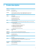
Table of contents 1 Product description ....................................................................................................................................... 1 2 External component identification .................................................................................................................. 3 Display ....................................................................................................................................................................
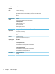
WLAN module .................................................................................................................................... 26 RTC battery ........................................................................................................................................ 28 Heat sink ............................................................................................................................................ 29 Speakers .................................................
11 Recycling .................................................................................................................................................. 58 Index .............................................................................................................................................................
viii
1 Product description Category Description Product Name HP Stream Laptop PC Model numbers: 14-ax0XX Processor Intel Celeron® N3060 (1.6 GHz, turbo up to 2.48 GHz), 1600 MHz/2 MB L2 cache), dual core, 4 W Intel Celeron N3050 (1.6 GHz, turbo up to 2.16 GHz), 1600 MHz/2 MB L2 cache), dual core, 4 W Chipset Integrated SoC Graphics Internal graphics Intel HD Graphics 400 (N3060 processor) Intel HD Graphics (N3050 processor) Support for DX12, HD decode, and HDMI Panel 16:9 ultra-wide aspect ratio 14.
Category Description Internal card expansion One M.2 card slot for WLAN Ports AC Smart Pin adapter plug Combo audio-out (headphone)/audio-in (microphone) jack High-definition multimedia interface (HDMI) v.1.4, supporting 1920×1080 at 60 Hz USB 3.0 (2) USB 2.
2 External component identification Display Component Description (1) Camera light On: The camera is in use. (2) Camera Allows you to video chat, record video, and record still images. (3) Internal microphone Records sound. (4) WLAN antennas* (1 or 2 depending on model) Send and receive wireless signals to communicate with wireless local area networks (WLANs). *The antennas are not visible from the outside of the computer, and antenna location varies.
Left side Component (1) Description Security cable slot Attaches an optional security cable to the computer. NOTE: The security cable is designed to act as a deterrent, but it may not prevent the computer from being mishandled or stolen. (2) HDMI port Connects an optional video or audio device, such as a highdefinition television, any compatible digital or audio component, or a high-speed High-Definition Multimedia Interface (HDMI) device. (3) USB 3.
Component (7) Description Power light ▲ Pull the card out of the memory card reader. ● On: The computer is on. ● Blinking: The computer is in the Sleep state, a powersaving state. The computer shuts off power to the display and other unneeded components. ● Off: The computer is off or in Hibernation. Hibernation is a power-saving state that uses the least amount of power.
Top TouchPad Component 6 Description (1) TouchPad zone Reads your finger gestures to move the pointer or activate items on the screen. (2) Left TouchPad button Functions like the left button on an external mouse. (3) Right TouchPad button Functions like the right button on an external mouse.
Lights Component Description (1) Caps lock light On: Caps lock is on, which switches the key input to all capital letters. (2) Mute light ● Amber: Computer sound is off. ● Off: Computer sound is on.
Button Component Power button Description ● When the computer is off, press the button to turn on the computer. ● When the computer is on, press the button briefly to initiate Sleep. ● When the computer is in the Sleep state, press the button briefly to exit Sleep. ● When the computer is in Hibernation, press the button briefly to exit Hibernation. CAUTION: Pressing and holding down the power button results in the loss of unsaved information.
Keys Component Description (1) esc key Displays system information when pressed in combination with the fn key. (2) fn key Executes specific functions when pressed in combination with the esc key. (3) Windows key Opens the Start menu. NOTE: Pressing the Windows key again will close the Start menu. (4) Action keys Execute frequently used system functions.
Using the action keys ● An action key performs an assigned function. ● The icon on each action key illustrates the function for that key. Icon Description Opens the Get started app. Decreases the screen brightness incrementally as long as you hold down the key. Increases the screen brightness incrementally as long as you hold down the key. Switches the screen image between display devices connected to the system.
Labels The labels affixed to the computer provide information you may need when you troubleshoot system problems or travel internationally with the computer. IMPORTANT: Check the following locations for the labels described in this section: the bottom of the computer, inside the battery bay, under the service door, or on the back of the display. ● Service label—Provides important information to identify your computer.
12 Item Description Function (4) Warranty period This number describes the duration of the warranty period for the computer. (5) Model description This is the alphanumeric identifier used to locate documents, drivers, and support for the computer. ● Regulatory label(s)—Provide(s) regulatory information about the computer.
3 Illustrated parts catalog NOTE: HP continually improves and changes product parts. For complete and current information on supported parts for your computer, go to http://partsurfer.hp.com, select your country or region, and then follow the on-screen instructions.
Item Component Spare part number (1) Display assembly: The display assembly is spared at the subcomponent level only. For more display assembly spare part information, see Display assembly components on page 16. (2) Keyboard/top cover (includes keyboard cable): For a list of keyboard country codes, see Keyboard/top cover on page 43 or Keyboard/top cover on page 43.
Item Component Spare part number For use in purple models 905690-001 For use in white models 910176-001 Memory module, 4 GB (PC3L, 12800, 1600-MHz; not illustrated)) 691740-005 Rubber Kit Item Description Spare part number Rubber Kit for use in blue models 905567-001 Rubber Kit for use in purple models 905739-001 Rubber Kit for use in white models 910179-001 (1) Top rubber foot/strip (2) Bottom rubber foot/strip Rubber Kit 15
Display assembly components 16 Item Description (1) Display bezel Spare part number For use in blue models 905559-001 For use in purple models 905689-001 For use in white models 910177-001 (2) Raw display panel 847664-005 (3) Webcam/microphone module 766523-025 (4) Display Hinge Kit (includes left and right display hinges) 905560-001 (5) Display panel cable 905561-001 (6) Antenna Kit (includes wireless antenna cable with transceiver) 906173-001 (7) Display back cover For use in
Miscellaneous parts Component Spare part number HP Smart AC adapter, 45-W, non-PFC, RC, 4.5-mm 741553-850 HP HDMI-to-VGA adapter 701943-001 HP USB to Gigabit RJ-45 Adapter 829941-001 HP USB external DVD±RW DL SuperMulti Drive 747080-001 Power cord (3-pin, black, 1.
4 Removal and replacement procedures preliminary requirements Tools required You will need the following tools to complete the removal and replacement procedures: ● Flat-bladed screw driver ● Magnetic screw driver ● Phillips P0 screw driver Service considerations The following sections include some of the considerations that you must keep in mind during disassembly and assembly procedures.
Grounding guidelines Electrostatic discharge damage Electronic components are sensitive to electrostatic discharge (ESD). Circuitry design and structure determine the degree of sensitivity. Networks built into many integrated circuits provide some protection, but in many cases, ESD contains enough power to alter device parameters or melt silicon junctions. A discharge of static electricity from a finger or other conductor can destroy static-sensitive devices or microcircuitry.
Packaging and transporting guidelines Follow these grounding guidelines when packaging and transporting equipment: ● To avoid hand contact, transport products in static-safe tubes, bags, or boxes. ● Protect ESD-sensitive parts and assemblies with conductive or approved containers or packaging. ● Keep ESD-sensitive parts in their containers until the parts arrive at static-free workstations. ● Place items on a grounded surface before removing items from their containers.
Equipment guidelines Grounding equipment must include either a wrist strap or a foot strap at a grounded workstation. ● When seated, wear a wrist strap connected to a grounded system. Wrist straps are flexible straps with a minimum of one megohm ±10% resistance in the ground cords. To provide proper ground, wear a strap snugly against the skin at all times. On grounded mats with banana-plug connectors, use alligator clips to connect a wrist strap.
5 Removal and replacement procedures for Authorized Service Provider parts NOTE: Components described in this chapter should only be accessed by an authorized service provider. Accessing these parts can damage the computer or void the warranty. NOTE: Details about your computer, including model, serial number, product key, and length of warranty, are on the service tag at the bottom of your computer. See Labels on page 11 for details. NOTE: HP continually improves and changes product parts.
Bottom cover Description Spare part number Bottom cover for use in blue models 905564-001 Bottom cover for use in purple models 905690-001 Bottom cover for use in white models 910176-001 Before removing the bottom cover, follow these steps: 1. Turn off the computer. If you are unsure whether the computer is off or in Hibernation, turn the computer on, and then shut it down through the operating system. 2. Disconnect the power from the computer by unplugging the power cord from the computer. 3.
Battery Description Spare part number Battery, 3-cell, 41-WHr, 3.615-AHr, Li-ion 844203-855 Battery cable 905566-001 Before removing the battery, follow these steps: 1. Shut down the computer. If you are unsure whether the computer is off or in Hibernation, turn the computer on, and then shut it down through the operating system. 2. Disconnect all external devices connected to the computer. 3.
Memory module Description Spare part number Memory module, 4 GB (PC3L, 12800, 1600-MHz) 691740-005 Before removing a memory module, follow these steps: 1. Shut down the computer. If you are unsure whether the computer is off or in Hibernation, turn the computer on, and then shut it down through the operating system. 2. Disconnect all external devices connected to the computer. 3.
WLAN module Description Spare part number Intel Dual Band Wireless-AC 7265 802.11 AC 2x2 WiFi + BT 4.2 Combo Adapter (non-vPro) 793840-005 CAUTION: To prevent an unresponsive system, replace the wireless module only with a wireless module authorized for use in the computer by the governmental agency that regulates wireless devices in your country or region. If you replace the module and then receive a warning message, remove the module to restore device functionality, and then contact technical support.
3. Remove the WLAN module (3) by pulling the module away from the slot at an angle. NOTE: If the WLAN antenna is not connected to the terminal on the WLAN module, a protective sleeve must be installed on the antenna connector, as shown in the following illustration. Reverse this procedure to install the WLAN module.
RTC battery Description Spare part number RTC battery 857380-001 Before removing the RTC battery, follow these steps: 1. Shut down the computer. If you are unsure whether the computer is off or in Hibernation, turn the computer on, and then shut it down through the operating system. 2. Disconnect all external devices connected to the computer. 3. Disconnect the power from the computer by first unplugging the power cord from the AC outlet and then unplugging the AC adapter from the computer. 4.
Heat sink Description Spare part number Heat sink 907105-001 Before removing the heat sink, follow these steps: 1. Shut down the computer. If you are unsure whether the computer is off or in Hibernation, turn the computer on, and then shut it down through the operating system. 2. Disconnect all external devices connected to the computer. 3. Disconnect the power from the computer by first unplugging the power cord from the AC outlet and then unplugging the AC adapter from the computer. 4.
Reverse this procedure to install the heat sink.
Speakers Description Spare part number Speakers (includes cable) 905565-001 Before removing the speakers, follow these steps: 1. Shut down the computer. If you are unsure whether the computer is off or in Hibernation, turn the computer on, and then shut it down through the operating system. 2. Disconnect all external devices connected to the computer. 3. Disconnect the power from the computer by first unplugging the power cord from the AC outlet and then unplugging the AC adapter from the computer.
System board Description Spare part number Intel Celeron N3060 processor, 2 GB system memory, 32 GB eMMC hard drive, and a non-Windows operating system 905302-001 Intel Celeron N3060 processor, 2 GB system memory, 32 GB eMMC hard drive, and the Windows 10 operating system 905302-601 Intel Celeron N3060 processor, 32 GB eMMC hard drive, and a non-Windows operating system 905305-001 Intel Celeron N3060 processor, 32 GB eMMC hard drive, and the Windows 10 operating system 905305-601 Intel Celeron N30
2. Remove the three black Phillips broad head PM2.0×2.5 screws (1) that secure the system board to the computer. 3. Remove the two silver Phillips PM2.0×2.5 screws (2) that secure the system board to the computer. 4. Lift up the left side of the system board (3), and then pull the system board toward the left to remove it from the computer (4). Reverse this procedure to install the system board.
TouchPad Description Spare part number TouchPad for use in blue models 905691-001 TouchPad for use in purple models 906174-001 TouchPad for use in white models 910178-001 TouchPad cable 905563-001 Before removing the TouchPad, follow these steps: 1. Turn off the computer. If you are unsure whether the computer is off or in Hibernation, turn the computer on, and then shut it down through the operating system. 2.
Display assembly NOTE: The display assembly is spared at the subcomponent level only. For display assembly spare part information, see the individual removal subsections. Before removing the display assembly, follow these steps: 1. Turn off the computer. If you are unsure whether the computer is off or in Hibernation, turn the computer on, and then shut it down through the operating system. 2. Disconnect the power from the computer by unplugging the power cord from the computer. 3.
5. If it is necessary to replace the webcam/microphone module: a. Detach and lift the module (1) from the display back cover. (The webcam/microphone module is attached to the display back cover with double-sided adhesive.) b. Disconnect the webcam/microphone module cable (2) from the module. The webcam/microphone module is available using spare part number 766523-025. 6. If it is necessary to replace the display panel: a. Remove the four Phillips PM2.0×3.
b. Lift the top edge of the display panel (2) and swing it up and forward until it rests upside down in front of the display back cover. The raw display panel is available using spare part number 847664-005. 7. c. Release the adhesive strip (1) that secures the display panel cable connector to the display panel. d. Disconnect the display panel cable (2) from the display panel. e. Remove the display panel from the computer (3).
a. Remove the two Phillips PM2.0×3.0 screws (1) on the top of the hinges. b. Remove the four Phillips PM2.5×2.5 screws (2) on the outside bottom of the hinges and the two Phillips PM2.5×4.0 screws (3) at the inside bottom of the hinges. c. Remove the display hinges (4). The display hinges are included in the Display Hinge Kit, spare part number 905560-001. 8. If it is necessary to replace the display panel cable: a.
b. Remove the display panel cable (2). The display panel cable includes the webcam/microphone module cable and is available using spare part number 905561-001. IMPORTANT: Be sure to note the way the cable routes into the display hinge, as shown in the following image. 9. If it is necessary to replace the WLAN antenna cable and transceiver: a. Release the antenna cable from the retention clips (1) and channel built into the right side of the display back cover.
b. Peel the antenna transceivers from the top of the display enclosure, and then remove the antennas from the enclosure (2). The antenna cables and transceivers are included in the WLAN Antenna Kit, spare part number 906173-001. IMPORTANT: Be sure to note the way the antenna cable routes into the display hinge, as shown in the following image. Reverse this procedure to reassemble and install the display assembly.
Power button board Description Spare part number Power button board 905579-001 Power button board cable 905562-001 Before removing the power button board, follow these steps: 1. Turn off the computer. If you are unsure whether the computer is off or in Hibernation, turn the computer on, and then shut it down through the operating system. 2. Disconnect the power from the computer by unplugging the power cord from the computer. 3. Disconnect all external devices from the computer. 4.
Power connector cable Description Spare part number Power connector cable 810327-004 Before removing the power connector cable, follow these steps: 1. Shut down the computer. If you are unsure whether the computer is off or in Hibernation, turn the computer on, and then shut it down through the operating system. 2. Disconnect all external devices connected to the computer. 3.
Keyboard/top cover The top cover/keyboard spare part remains after all other spare parts have been removed. In this section, the first table provides the main spare part number for the keyboards. The second table provides the country codes.
6 Using Setup Utility (BIOS) Setup Utility, or Basic Input/Output System (BIOS), controls communication between all the input and output devices on the system (such as disk drives, display, keyboard, mouse, and printer). Setup Utility (BIOS) includes settings for the types of devices installed, the startup sequence of the computer, and the amount of system and extended memory.
Downloading a BIOS update CAUTION: To reduce the risk of damage to the computer or an unsuccessful installation, download and install a BIOS update only when the computer is connected to reliable external power using the AC adapter. Do not download or install a BIOS update while the computer is running on battery power, docked in an optional docking device, or connected to an optional power source.
7 Specifications Computer specifications Metric U.S. Width 33.7 cm 13.27 in Depth 22.6 cm 8.90 in Height 1.79 cm 0.71 in Weight 1.44 kg 3.18 lbs Input power Operating voltage and current 19.5 V dc @ 2.31 A – 45 W 19.5 V dc @ 3.
35.56-cm (14.0-in), HD display specifications Metric U.S. Active diagonal size 35.56-cm 14.0-in Resolution 1366x768 (HD) Width 3.0 mm Surface treatment BrightView Brightness 220 nits (typical) Viewing angle SVA Backlight LED 35.56-cm (14.
8 Backing up, restoring, and recovering This chapter provides information about the following processes. The information in the chapter is standard procedure for most products. ● Creating recovery media and backups ● Restoring and recovering your system For additional information, refer to the HP support assistant app. ▲ Type support in the taskbar search box, and then select the HP Support Assistant app. ‒ or – Click the question mark icon in the taskbar.
You can use Windows tools to create system restore points and create backups of personal information, see Using Windows tools on page 49. ● If your computer does list the Recovery partition and the Windows partition, you can use HP Recovery Manager to create recovery media after you successfully set up the computer. HP Recovery media can be used to perform system recovery if the hard drive becomes corrupted.
Restore and recovery There are several options for recovering your system. Choose the method that best matches your situation and level of expertise: IMPORTANT: ● Windows offers several options for restoring from backup, refreshing the computer, and resetting the computer to its original state. For more information see the Get started app. ▲ ● Not all methods are available on all products. Select the Start button, and then select the Get started app.
website. Go to http://www.hp.com/support, select your country or region, and follow the on-screen instructions. IMPORTANT: HP Recovery Manager does not automatically provide backups of your personal data. Before beginning recovery, back up any personal data you want to retain. Using HP Recovery media, you can choose from one of the following recovery options: NOTE: Only the options available for your computer display when you start the recovery process.
1. If possible, back up all personal files. 2. Insert the HP Recovery media, and then restart the computer. NOTE: If the computer does not automatically restart in HP Recovery Manager, change the computer boot order. See Changing the computer boot order on page 52. 3. Follow the on-screen instructions.
Removing the HP Recovery partition (select products only) HP Recovery Manager software allows you to remove the HP Recovery partition to free up hard drive space. IMPORTANT: After you remove the HP Recovery partition, you will not be able to perform System Recovery or create HP recovery media from the HP Recovery partition. So before you remove the Recovery partition, create HP Recovery media; see Creating HP Recovery media (select products only) on page 48.
9 Using HP PC Hardware Diagnostics (UEFI) HP PC Hardware Diagnostics is a Unified Extensible Firmware Interface (UEFI) that allows you to run diagnostic tests to determine whether the computer hardware is functioning properly. The tool runs outside the operating system so that it can isolate hardware failures from issues that are caused by the operating system or other software components.
3. Enter the product name or number. – or – Select Identify now to let HP automatically detect your product. 4. Select your computer, and then select your operating system. 5. In the Diagnostic section, follow the on-screen instructions to select and download the UEFI version you want.
10 Power cord set requirements The wide-range input feature of the computer permits it to operate from any line voltage from 100 to 120 volts AC, or from 220 to 240 volts AC. The 3-conductor power cord set included with the computer meets the requirements for use in the country or region where the equipment is purchased. Power cord sets for use in other countries and regions must meet the requirements of the country or region where the computer is used.
Country/region Accredited agency Applicable note number South Korea EK 4 Sweden CEMKO 1 Switzerland SEV 1 Taiwan BSMI 4 The United Kingdom BSI 1 The United States UL 2 1. The flexible cord must be Type HO5VV-F, 3-conductor, 1.0-mm² conductor size. Power cord set fittings (appliance coupler and wall plug) must bear the certification mark of the agency responsible for evaluation in the country or region where it will be used. 2. The flexible cord must be Type SPT-3 or equivalent, No.
11 Recycling When a non-rechargeable or rechargeable battery has reached the end of its useful life, do not dispose of the battery in general household waste. Follow the local laws and regulations in your area for battery disposal. HP encourages customers to recycle used electronic hardware, HP original print cartridges, and rechargeable batteries. For more information about recycling programs, see the HP Web site at http://www.hp.com/recycle.
Index A AC adapter and battery 5 AC adapter, spare part number 17 action keys 10 identifying 9 airplane mode key 10 antenna removal 39 spare part number 16, 40 Antenna Kit, spare part number 16, 40 audio, product description 1 audio-out (headphone)/audio-in (microphone) jack, identifying 4 B backups 48 base enclosure, spare part number 14 battery removal 24 spare part number 14, 24 battery cable spare part number 14, 24 BIOS determining version 44 downloading an update 45 starting the Setup Utility 44 updat
K keyboard/top cover removal 43 spare part numbers keys action 9 airplane mode 10 esc 9 fn 9 Windows 9 14, 43 L labels Bluetooth 12 regulatory 12 serial number 11 service 11 wireless certification 12 WLAN 12 lights AC adapter and battery light 5 caps lock 7 mute 7 power 5 M memory card reader, identifying 4 memory card, identifying 4 memory module removing 25 memory, product description 1 microphone product description 1 minimized image recovery 51 minimized image, creating 50 model name 1 mute light, ide
system board removal 32 spare part numbers 32 system recovery 50 system restore point creating 49 system restore point, creating 48 T tools required 18 TouchPad buttons 6 removal 34 spare part number 14, 34 TouchPad cable spare part number 14, 34 TouchPad zone, identifying 6 transporting guidelines 20 traveling with the computer 12 U USB 2.0 port, identifying USB 3.