
Compaq 325 and 326 Notebook PCs HP 425 and 625 Notebook PCs - Maintenance and Service Guide
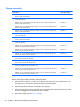

5. Remove the service door (see Service door on page 49).
6. Remove the palm rest (see
Palm rest on page 64).
7. Remove the keyboard (see
Keyboard on page 67).
8. Remove the top cover (see
Top cover on page 71).
Remove the display on 39.6-cm (15.6-in) computers:
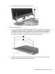
1. Orient the computer in its normal position, face up with the display open as far as it will
comfortably go.
CAUTION: Support the display assembly when removing the retaining screws. Failure to
support the display assembly can result in damage to the display assembly and other computer
components.
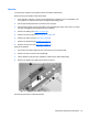
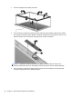
2. Disconnect the display cable (1) and the microphone cable (2) from the system board.
3. Release the WLAN cables from the cable run (3), being careful when pulling them through the
opening near the hard drive.
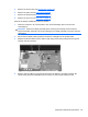
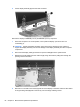
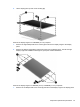
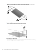
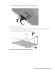
4. Remove eight Torx M2.5×6.0 screws (1) that secure the display to the base enclosure. Be
careful of the grounding cable (2) that is secured by one of the hinge retaining screws.
Component replacement procedures 83