HP XP24000/XP20000 Continuous Access Journal Software User Guide Abstract This guide explains how to use HP XP Continuous Access Journal Software to replicate data between local and remote HP XP disk arrays and to achieve disaster tolerance with maximum application performance. Topics include setting up remote copy connections, configuring the storage system, creating and monitoring remote copies, recovering from a disaster, and troubleshooting.
© Copyright 2007, 2011 Hewlett-Packard Development Company, L.P. Confidential computer software. Valid license from HP required for possession, use or copying. Consistent with FAR 12.211 and 12.212, Commercial Computer Software, Computer Software Documentation, and Technical Data for Commercial Items are licensed to the U.S. Government under vendor's standard commercial license. The information contained herein is subject to change without notice.
Contents 1 Overview of HP XP Continuous Access Journal Software..................................8 XP Continuous Access Journal....................................................................................................8 Features..................................................................................................................................9 Benefits...................................................................................................................................
3 Preparing for XP Continuous Access Journal Operations................................43 Requirements and Restrictions...................................................................................................43 System Requirements..........................................................................................................43 One-to-One Volume Copy Operations..................................................................................45 Logical Unit (LU) Types......................
Requirements for Creating an XP Continuous Access Journal Pair for the Delta Resync Operation....................................................................................................................89 Requirements for Performing the Delta Resync Operation....................................................89 Configuring Delta Resync Operation Environment that uses Remote Command Devices...........91 Changing to a 3DC Multi-Target Configuration After Recovering from Primary Site Failures.....
Adding Logical Paths............................................................................................................150 Viewing the Status of Logical Paths..........................................................................................152 Deleting Logical Paths...........................................................................................................154 Managing Power for Storage Systems and Network Relay Devices..............................................
Transferring Operations Back to the Primary Site..................................................................204 Resuming Normal Operations at the Primary Site.................................................................205 Recovering from Primary Site Failures in XP Continuous Access Journal 3DC Multi-Target Configuration (When Delta Resync Operation is Performed)...........................................................................
1 Overview of HP XP Continuous Access Journal Software This chapter provides an overview of HP XP Continuous Access Journal Software and describes its features and benefits.
Features XP Continuous Access Journal provides the following key features: • • Heterogeneous Storage System Support ◦ Used with the storage system, XP Continuous Access Journal software enables storage management and disaster recovery in heterogeneous systems, providing maximum flexibility and support of enterprise-class environments.
• • ◦ Reduces overhead and application impact at the production site by placing more of the workload on the remote site ◦ Centralizes operations for management resources and provides secure management of data-related operational risk Improve Operational Efficiency and Resiliency ◦ Simplifies consolidation/aggregation and mapping of data value to the cost of storage ◦ Supports planned site outages ◦ Keeps logging changes in the event of network problems between sites ◦ Reduces costs—requires onl
2 About XP Continuous Access Journal Operations This chapter describes how XP Continuous Access Journal provides a storage-based, XP hardware solution for disaster recovery that enables fast and accurate system recovery.
Figure 1 XP Continuous Access Journal Operations for a Fibre Channel Connection Journal Obtain Journal obtain is the function that stores data from the primary data volume as a base-journal in the primary site journal volume. The journal obtain function, with every update of the primary data volume according to the write instruction from the host, then stores the write data as journal data in the journal volume.
data volume according to the write sequence number. This will ensure write sequence consistency between the primary and secondary data volumes. After the journal data is restored to the secondary data volume, the journal data is discarded at the secondary site.
Figure 3 Configuration for Multiple Secondary Storage Systems Storage Systems XP Continuous Access Journal operations involve the storage systems at the primary and secondary sites. The primary storage system consists of the main control unit (primary storage system) and SVP. The secondary storage system consists of the remote control unit (secondary storage system) and SVP.
system). This virtual storage system is called a logical DKC or an LDKC (logical disk controller). There is one LDKC in the storage system, and number 00 is assigned to the LDKC. Each LDKC controls 255 CUs. However, the number of CUs that can be used for storage system program products is up to 255. Therefore, the maximum number of volumes that can be used for storage system program products is 65,280 volumes for an LDKC.
The specifications for consistency group numbers are different from the specifications for journal group numbers. One storage system has a total of 256 (0 to 255) consistency groups for the primary and secondary data volumes (numbers 0 to 255) are assigned). Note: The consistency group number of the primary and secondary data volumes to be paired must be same.
The XP Continuous Access Journal remote copy configuration between the primary storage system and secondary storage system has the following requirement (see “Setting up Remote Copy Connections” (page 52)): • XP Continuous Access Journal supports a 1-to-1 remote copy connection in one journal group pair. In one journal group pair, one primary storage system can be connected to only one secondary storage system.
Caution: Data volumes and journal volumes that belong to different LDKCs cannot coexist in a journal group. For detailed information about the specification of journal groups, see “Journal Group Specifications” (page 48). Data Volume Pairs XP Continuous Access Journal performs remote copy operations for data volume pairs created by the user. Each XP Continuous Access Journal pair consists of one primary data volume and one secondary data volume, which can be located in different storage systems.
Table 2 Emulation Types for Journal Volumes Emulation Category Supported Emulation Types DKU (drive) OPEN-V Note: You can only use OPEN-V volumes for journal volumes. • Volumes and their capacity: You can use CVS volumes for journal volumes. Journal volumes in the same journal group can have different capacities. A master journal volume and the corresponding restore journal volume can have different capacities.
Adding journal volumes during a remote copy operation may not change the journal data usage rate until the journal volumes are used. To check the journal data usage rate, use the Usage Monitor window (see “Usage Monitor Operations” (page 197)).
XP Continuous Access Journal Remote Copy Operations This section describes the remote copy operations using XP Continuous Access Journal. Figure 5 (page 21) illustrates the two types of XP Continuous Access Journal remote copy operations: initial copy and update copy. Figure 5 Remote Copy Operations This section describes the following topics that are related to remote copy operations with XP Continuous Access Journal.
The base-journal data is stored in the entire data volume or the area for the difference. The journal data for the entire data volume is created when the data volume pair is created. The difference journal data is obtained when the pair status of the data volume changes from the Suspending status to the Pair resync status. Merging the difference bitmaps that are recorded on both primary and secondary data volumes enables you to obtain the journal data for only the difference.
is written to the primary data volume is obtained as an update journal. The update journal is copied to the secondary storage system, and then restored to the secondary data volume. The primary storage system obtains the update data that the host writes to the primary data volume as update journals. • Update journals are stored in journal volumes in the journal group of the primary data volume.
primary storage system does not read the XP Continuous Access Journal secondary data volume for a recovery. Write and Update Copy / Write Failure When a primary storage system receives a write I/O for a primary data volume with PAIR status, the operation is executed at the primary storage system. The primary storage system completes the primary data volume write operations independently of the update copy operations at the secondary data volume.
Difference Management The differential data (updated by write I/Os during a split or suspension) between the primary data volume and the secondary data volume is stored in each track bitmap. When a split/suspended pair is resumed (pairresync), the primary storage system merges the primary data volume and secondary data volume bitmaps, and the differential data is copied to the secondary data volume.
secondary data volume in the same order as the primary data volume, according to the sequence number information in the journal. Note: XP Continuous Access Journal processing continues uninterrupted if the SVP reboots or even if the SVP fails. Types of Journals In addition to the journal data for updating, the primary storage system sends control information to the secondary storage system.
When journal data S2 arrives, the secondary storage system selects S2 as the next journal data to be settled. The journal data selected by the secondary storage system is marked as host-dirty and treated as formal data.
by the delta resync operation; you need not wait long before you can again access the XP Continuous Access Journal data volumes. A delta resync operation consists of two processes: preparation before the failure occurs (see “Journal Obtain at XP Continuous Access Synchronous Secondary Site” (page 28)) and the recovery after a failure has occurred (see “Switching the Master Journal Group of XP Continuous Access Journal” (page 30)).
Figure 7 Delta Resync Setting 3DC Multi-Target Configuration - Before Failure Occurs As shown in Figure 7 (page 29), an XP Continuous Access Journal pair created with the delta resync operation is defined as a pair (HOLD status) but an actual copy operation is not performed until the failure occurs and the delta resync operation is performed. There are several requirements to create an XP Continuous Access Journal pair for the delta resync operation, such as specifying the unused mirror ID.
obtained in the XP Continuous Access Synchronous secondary site because of the failure in the master journal volume or occurrence of the pinned track. If the status of the XP Continuous Access Journal pair for the delta resync operation changes to HLDE, follow the steps in “Restoring a Pair of Data Volumes (Pairresync)” (page 191) and change the pair status to HOLD again.
Figure 8 Delta Resync Setting 3DC Multi-Target Configuration - After Failure Occurs For the latest information on the availability of the delta resync function, contact HP technical support. As illustrated in Figure 8 (page 31), after a failure occurs in primary site A, the horctakeover command is used to reconfigure the former XP Continuous Access Synchronous secondary site as the primary site B.
In the delta resync operation, the status of the XP Continuous Access Journal pair changes to PAIR (not COPY). This is because the delta resync operation uses journal copy to copy only the missing journal data instead of copying all the data in the primary volume. Therefore, the delta resync operation requires less time to recover the XP Continuous Access Journal pair after a failure occurs.
You can view the detailed pair status information at the Remote Web Console computer (XP Continuous Access Journal Detailed Information window) or at the UNIX/Computer server host (RAID Manager Pairdisplay command). Table 4 (page 33) shows the relationships.
When an XP Continuous Access Journal data volume pair is split or suspended, the primary storage system generates a service information message (SIM) to notify the host(s). If SNMP is installed and operational for the storage system, this SIM results in an SNMP trap that indicates the reason for suspension.
Table 5 XP Continuous Access Journal Data Volume Pair Status (continued) Pair Status Description Primary Data Volume Access PAIR This data volume pair is synchronized. Updates Read / Write to the primary data volume are duplicated on the secondary data volume.
Table 5 XP Continuous Access Journal Data Volume Pair Status (continued) Pair Status Description Primary Data Volume Access Secondary Data Volume Access status is normal) and changes the primary data volume status to PSUS. PFUL In this status, the amount of data in the journal Read / Write volume exceeds the threshold (80%). The pair status changes from PAIR to PFUL. The XP Continuous Access Journal pair is not suspended and the copy is continued.
Table 5 XP Continuous Access Journal Data Volume Pair Status (continued) Pair Status Description Primary Data Volume Access Deleting (releasing) This pair is not synchronized. This pair is in transition from PAIR, COPY, or PSUS/PSUE to SMPL. When the pairsplit-S operation is requested, the status of all affected pairs changes to Deleting (releasing). When the pairsplit-S operation is complete, the status changes to SMPL.
*4: HOLDING indicates that the differential data to be used for a delta resync operation either does not exist in the storage system, or either the storage system cannot determine whether the delta resync operation can be performed without the differential data to be used for a delta resync operation.
Resume Pair – Synchronization: When the pair is resumed (pairresync), the secondary storage system sends the secondary data volume track bitmap to the primary storage system, and the primary storage system merges the primary data volume and secondary data volume bitmaps to determine which tracks are out-of-sync. Consistency Status: A split (or suspended) XP Continuous Access Journal secondary data volume has an additional status called the consistency status.
Table 7 Consistency Status for Split/Suspended XP Continuous Access Journal Secondary Data Volumes (continued) Consistency Status (shown at secondary storage system) Description Access Journal data volume pair from the secondary storage system). This status is indicated when: • This pair was split by the user using the Suspend Range-Group pairsplit option. • All pairs in this journal group were suspended due to a failure that affected the entire journal group (not just one pair).
Table 8 Suspend Types (PSUE) (continued) Type Applies to Description In this case, the secondary data volume suspend type is usually PSUE-S-VOL Failure. PSUE, MCU IMPL Primary data volume, The primary storage system could not find valid control information Secondary data volume in its nonvolatile memory during an IMPL. This condition occurs only if the primary storage system is without power for more than 48 hours (that is, a power failure and fully discharged backup batteries).
Table 9 XP Continuous Access Journal Suspension Condition Suspension Condition 42 Detected by XP Continuous Access Journal Pairs to be Suspended The secondary storage system could not copy the RCU journal data successfully due to a hardware failure or logic error. All XP Continuous Access Journal secondary data volumes in the journal groups, or the affected secondary data volume The secondary storage system detected a logical error RCU while selecting the journal data to be restored.
3 Preparing for XP Continuous Access Journal Operations This chapter describes the prerequisites and preparations to make to begin operations: • “Requirements and Restrictions” (page 43) • “Installing the Hardware” (page 51) • “Configuring the Primary and Secondary Storage Systems for XP Continuous Access Journal Operations” (page 53) • “Using Multiple Primary and Secondary Storage Systems” (page 55) • “Enabling the XP Continuous Access Journal Option” (page 71) • “Interoperability with Other Pro
and remote sites, and the licensed XP Continuous Access Journal remote console software. The XP Continuous Access Journal system requirements are: • Primary storage system−storage system with XP Continuous Access Journal installed. • Secondary storage system−storage system with XP Continuous Access Journal installed. XP Continuous Access Journal can coexist with Hitachi TrueCopy™ for Mainframe in the same storage system.
When running the 3DC system. In addition, you also need a license for Disaster Recovery Extended in the following cases: • ◦ When performing the remote copy operation in the system that consists of multiple primary and secondary storage systems. ◦ When you use a virtual volume of XP Thin Provisioning (TP-VOL) for XP Continuous Access Journal P-VOL or S-VOL, the capacity of the allocated pages for TP-VOL is counted as the licensed capacity of XP Continuous Access Journal.
Table 11 (page 46) lists the volumes and the volume capacity that can be used for the XP Continuous Access Journal data volume and journal volume. Remember that the capacity of journal volume is not included in the accounting capacity.
Table 14 RAID Level Configuration of XP Continuous Access Journal Item Support Specifications RAID configuration of the data volume and journal volume RAID1, RAID5, and RAID6 can coexist. RAID1, RAID5, and RAID6 can coexist in the same journal group. Maximum Number of Pairs The number of pairs that can be created in a storage system is limited. Use the number of cylinders and bitmap areas to calculate the maximum number of pairs that can be created in a storage system.
Table 15 Relationship Between Additional Shared Memory and Total Number of Bitmap Areas in the Storage System Additional Shared Memory for XP Continuous Access Journal Total Number of Bitmap Areas in the Storage System No additional shared memory for XP Continuous Access Journal 0 Additional shared memory for XP Continuous Access Journal is installed 7,424 Extension 1 16,384 Extension 2 32,768 Extension 3 (available only for XP24000 Disk Array) 44,256 Extension 4 (available only for XP24000 Disk A
Table 16 Journal Group Specifications (continued) Item Support Specifications depends on the number of data volumes that can be registered to a journal group of the paired storage system. Number of journal volumes in a journal group Up to 64 Capacity of journal volumes in journal group At least 6GB.
about the case when the system option mode 707 is set to ON, see “XP Continuous Access Synchronous (2DC Configuration)” (page 100). If the system option mode 767 is set to ON when you registered the journal group, the mode 767 setting is always applied even if you change the option mode to OFF afterward.
volumes and asked which volume should be left offline. This can be confusing and prone to error. • If the XP Continuous Access Journal secondary data volumes and primary data volumes are connected to the same host(s), HP strongly recommends that the secondary data volumes are defined to remain offline to avoid this problem. Installing the Hardware Initial installation of the XP Continuous Access Journal hardware is performed by the user and the HP service representative.
Setting up Remote Copy Connections Figure 9 (page 52) shows the remote copy connection configurations for XP Continuous Access Journal operations. The primary storage system and secondary storage system for each XP Continuous Access Journal pair must be connected via optical fiber cables. • If you use multimode short-wave optical fiber cables, fibre cables up to 1.5 km in length and up to two switches are required for distances greater than 0.5 km.
Figure 10 Direct Remote Copy Connections * To set ports, use LUN Manager and set the port topology to Fabric off, FC-AL. Figure 11 Switch Remote Copy Connections Figure 12 Extender Remote Copy Connections Caution: When an MCU and RCU are connected via switches with a channel extender, and multiple remote copy paths are assembled, the capacity of the data to be transmitted may concentrate on particular switches, depending on the configuration and the settings of the switch routing.
1. 2. 3. Identify the volumes that will become the XP Continuous Access Journal data volumes and journal volumes in the primary storage system and secondary storage system. • You need to know the storage system S/N and port ID so that you can configure the primary storage systems and secondary storage systems correctly for your desired pairs. • When you create the pairs, you will need to know the port, group ID (GID), and LUN for each volume.
Using Multiple Primary and Secondary Storage Systems System configuration of up to four primary storage systems and up to four secondary storage systems is allowed for XP Continuous Access Journal operations. Even when there are multiple primary and secondary storage systems, XP Continuous Access Journal can copy the data in the primary storage system to the secondary storage system, while maintaining consistency in data update sequence.
Figure 14 Example 1: When the Consistency Group Contains Multiple Journal Groups Figure 15 Example 2: When the Consistency Group Contains Multiple Journal Groups 56 Preparing for XP Continuous Access Journal Operations
Figure 16 Example 3: When the Consistency Group Contains Multiple Journal Groups Basic Behavior When Using Multiple Primary and Secondary Storage Systems This section explains the basic behavior of XP Continuous Access Journal under the following conditions: • There are two primary storage systems and two secondary storage systems. • Two storage systems are defined in the RAID Manager configuration definition file. • All XP Continuous Access Journal pairs are in PAIR status.
4. 5. 6. 7. 8. 9. this point, two kinds of information, the time stamp information issued from RAID Manager and the sequence number indicating the write order, are added to the journal data. The journal copy function allows XP Continuous Access Journal to copy the journal data in the primary journal volume to the paired restore journal volume. Journal copying is performed asynchronously with journal obtaining.
If the above-mentioned conditions are all fulfilled, and when an error occurs to one of the journal groups, the error will be communicated to other journal groups. If you use RAID Manager, and if a journal group is in the normal status, it will be shown as PJNN. When an error occurs, the status of the journal group changes from normal to PJSE. In case of the capacity overflowing, the status changes to PJSF.
Figure 18 Flow of Transferring the Business Tasks from the Remote to Primary Site When the System Consists of Multiple Primary and Secondary Storage Systems 3DC Multi-target Configuration of Three XP Continuous Access Journal Sites You can set the system option mode 767 in the XP24000/XP20000 disk arrays. If you set the system option mode 767 to ON in each of the three sites and then register new journal groups, you can define a multi-target configuration combining three sites.
Access Journal secondary sites are combined, you can create a XP Continuous Access Journal pair for delta resync operation. If you create a XP Continuous Access Journal pair for delta resync operation, you can restart your business tasks by duplicating volumes in a short time without a long disaster recovery operation that copies all volumes in the site. The following figure shows a 3DC multi-target configuration where three XP Continuous Access Journal sites are combined.
6. 7. 8. Create an XP Continuous Access Journal pair of the second mirror in the primary site. Specify the primary journal group and the primary data volume used for the first mirror as the primary journal group and the primary data volume of the XP Continuous Access Journal pair. Select any mirror ID from 0 to 3 except the one used in Step 4. Wait until the status of the XP Continuous Access Journal pair becomes PAIR.
• When the primary data volume of the XP Continuous Access Journal pair of the first mirror is in COPY status, the pair of the second mirror cannot be created. • When multiple mirrors are registered in the journal group, if the primary data volume of the pair of one mirror is in COPY status, the pair of another mirror cannot be resynchronized.
requirements. In the following cases, delta resync operation will not be performed because the necessary journal data does not exist when: ◦ After splitting the XP Continuous Access Journal pair, the secondary data volume of the XP Continuous Access Journal pair associated with the secondary data volume of the XP Continuous Access Journal pair for delta resync operation is updated.
4. 5. 6. Execute the delta resync command (pairresync –swaps) on the XP Continuous Access Journal pair for delta resync operation in the primary site. The storage system reverses the primary and the secondary data volumes to restore and resynchronize the pair. Confirm the execution result of the delta resync command (pairresync –swaps). The XP Continuous Access Journal pair for delta resync becomes the XP Continuous Access Journal primary data volume.
3DC cascading configuration where three XP Continuous Access Journal sites are combined.
7. 8. as the primary journal group and the primary data volume of the XP Continuous Access Journal pair. Select any mirror ID from 0 to 3 except the one used in Step 4. Wait until the status of the XP Continuous Access Journal pair becomes PAIR. Create an XP Continuous Access Journal pair for delta resync operation by using the data volumes in the primary and the secondary sites.
Notes on performing Delta Resync Operations Before performing delta resync operations, specify an XP Continuous Access Journal pair belonging to the journal group whose XP Continuous Access Journal pairs meets the following requirements: NOTE: In the journal group, even if the specified pair satisfies requirements, an error may occur when any XP Continuous Access Journal pair does not satisfy the requirements. • Status of the primary data volume is HOLD.
delta resync operation will not be performed because the necessary journal data does not exist when: • After splitting the XP Continuous Access Journal pair, the secondary data volume of the XP Continuous Access Journal pair associated with the secondary data volume of the XP Continuous Access Journal pair for delta resync operation is updated • After splitting a XP Continuous Access Journal pair and as a result of the update of the primary data volume, the capacity of the journal data exceeds 70% of the
5. Resynchronize the XP Continuous Access Journal pair between the intermediate site and the secondary site. Figure 22 Configuration when Transferring Business Tasks from the XP Continuous Access Journal Intermediate Site to the Primary Site Restoring the XP Continuous Access Journal Intermediate site and the Cascading Configuration If you remove failures from the intermediate site, you can transfer your business tasks back to the primary site using RAID Manager and the following procedure: 1.
Figure 23 Configuration when Restoring the XP Continuous Access Journal Intermediate Site and the Cascading Configuration Enabling the XP Continuous Access Journal Option To operate the XP Continuous Access Journal software, a computer for Remote Web Console is required. For further information on Remote Web Console operations, see the HP XP24000/XP20000 Remote Web Console User Guide or contact your HP service representative.
Table 19 Whether Non-XP Continuous Access Journal Volumes Can Be Used as XP Continuous Access Journal Volumes Functions and Volumes Can the Volumes Be Used as Primary Data Volumes? Can the Volumes Be Used as Secondary Data Volumes? Can the Volumes Be Used as Journal Volumes? Yes Yes No P-VOL in PSUS status Yes Yes No P-VOL in COPY(RS-R) status No No No P-VOL that is also used as an XP Continuous Access P-VOL or XP Continuous Access S-VOL Yes Yes No P-VOL (none of the above) Yes Yes No
Table 19 Whether Non-XP Continuous Access Journal Volumes Can Be Used as XP Continuous Access Journal Volumes (continued) Functions and Volumes Can the Volumes Be Used as Primary Data Volumes? Can the Volumes Be Used as Secondary Data Volumes? Can the Volumes Be Used as Journal Volumes? V-VOL No No No Pool-VOL No No No Yes3 Yes3 No Yes Yes No No No No P-VOL in COPY status No No No P-VOL in PAIR status Yes4 No No P-VOL in PSUS status Yes4 No2 No P-VOL in PSUE status Yes4 No
Table 19 Whether Non-XP Continuous Access Journal Volumes Can Be Used as XP Continuous Access Journal Volumes (continued) Functions and Volumes Can the Volumes Be Used as Primary Data Volumes? Can the Volumes Be Used as Secondary Data Volumes? Can the Volumes Be Used as Journal Volumes? Yes4 No No No No No Volume with the Read/Write attribute Yes Yes Yes Volume with the Protect attribute Yes Yes No Volume with the Read Only attribute Yes Yes No Volume that is disabled for use as an S-V
Table 19 Whether Non-XP Continuous Access Journal Volumes Can Be Used as XP Continuous Access Journal Volumes (continued) Functions and Volumes Can the Volumes Be Used as Primary Data Volumes? Can the Volumes Be Used as Secondary Data Volumes? Can the Volumes Be Used as Journal Volumes? Yes Yes Yes Volume to which a path is defined Yes Yes No Volume to which no path is defined No No No Volume to which LUN security is applied Yes Yes No Yes Yes No Virtual LUN volume LUN Manager XP Thin
Journal primary data volume or secondary data volume, you must delete the pair first to return the volume to SMPL status. When creating an XP Continuous Access Journal pair consisting of two Virtual LUN volumes, make sure that the primary data volume and secondary data volumes have the same capacity. Cache Residency Manager You can perform Cache Residency Manager operations on XP Continuous Access Journal primary data volumes and secondary data volumes.
Table 20 (page 77) describes the host pair status reporting for XP Continuous Access Journal volumes, XP Business Copy volumes, and XP Continuous Access Journal/XP Business Copy shared volumes. Table 21 (page 77) shows the currency of the data on a shared XP Continuous Access Journal/XP Business Copy volume based on the XP Continuous Access Journal and XP Business Copy pair status.
Figure 24 Shared XP Continuous Access Journal Primary Data Volume and XP Business Copy P-VOL • XP Continuous Access Journal/XP Business Copy configurations that share the XP Continuous Access Journal secondary data volume and XP Business Copy P-VOL Figure 25 (page 78) shows an example of an XP Continuous Access Journal secondary data volume that is also functioning as an XP Business Copy P-VOL.
Figure 26 Shared XP Continuous Access Journal Primary Data Volume and XP Business Copy P-VOL, and XP Continuous Access Journal Secondary Data Volume and XP Business Copy P-VOL • XP Continuous Access Journal/XP Business Copy configuration where an XP Business Copy S-VOL in PSUS status is used as an XP Continuous Access Journal primary data volume In the following example, an XP Business Copy S-VOL in PSUS status is also functioning as an XP Continuous Access Journal primary data volume.
8. 9. Execute the RAID Manager pairsplit -r command on the XP Business Copy pair to put the pair in PSUS status (see Figure 35 (page 81)). Execute the RAID Manager paircreate command on the XP Continuous Access Journal pair to recreate the pair (see Figure 36 (page 82)).
Figure 32 Restoring an XP Business Copy P-VOL - Step 5 Figure 33 Restoring an XP Business Copy P-VOL - Step 6 Figure 34 Restoring an XP Business Copy P-VOL - Step 7 Figure 35 Restoring an XP Business Copy P-VOL - Step 8 Interoperability with Other Products and Functions 81
Figure 36 Restoring an XP Business Copy P-VOL - Step 9 XP Continuous Access Synchronous (3DC Cascading Configuration) The XP24000/20000 Disk Array provides a function to combine XP Continuous Access Journal and XP Continuous Access Synchronous. This combination is intended to ensure that the response time against host I/Os is comparable, regardless of whether the distance between the primary and the secondary sites are short or long.
Note that the 3DC cascading configuration of XP Continuous Access Journal and XP Continuous Access Synchronous is not available in the system that consists of multiple primary and secondary storage systems. The response time for host I/Os will roughly be the sum of the response time for XP Continuous Access Synchronous operation and the creation time of journal data in an intermediate site.
Figure 38 Basic Behavior in a 3DC Cascading Configuration Use differential copy, in a 3DC cascading configuration, to resynchronize either a suspended XP Continuous Access Synchronous or a suspended XP Continuous Access Journal pair. To perform disaster recovery from a failure at the primary site in a 3DC cascading configuration, you must ensure that the fence level of the XP Continuous Access Synchronous P-VOL is Data.
1. 2. 3. 4. Install XP Continuous Access Synchronous and XP Continuous Access Journal. Configure the ports and journal groups. Issue a request for creating an XP Continuous Access Synchronous pair to the primary storage system where XP Continuous Access Synchronous is installed. Wait until the status of the XP Continuous Access Synchronous pair becomes PAIR. Issue a request for creating an XP Continuous Access Journal pair to the XP Continuous Access Journal primary storage system.
Figure 39 3DC Multi-Target Configuration (Combining XP Continuous Access Journal with XP Continuous Access Synchronous) In this configuration, the primary volume at the primary site is paired with the secondary volume for XP Continuous Access Synchronous. This primary volume is also paired with the secondary volume for XP Continuous Access Journal.
Multi-Target Configuration” (page 210) and “Changing to a 3DC Multi-Target Configuration After Recovering from Primary Site Failures” (page 93). If a failure occurs in both the primary volume and the XP Continuous Access Synchronous secondary volume, you can resume your business tasks by using the XP Continuous Access Journal secondary data volume.
Access Journal pair for the delta resync operation. For details, see “Recovering from Primary Site Disaster in a 3DC Multi-Target Configuration” (page 210). ◦ • To use the delta resync function that uses remote command devices, a remote command device must be created on the XP Continuous Access Synchronous primary site and the XP Continuous Access Journal secondary site. For details about creating a remote command device, see the HP XP24000/XP20000 External Storage Software User Guide.
If you release the XP Continuous Access Synchronous pair created in step 2, the XP Continuous Access Journal pair created in step 6 will be released as well. In addition, if you release the XP Continuous Access Journal pair created in step 4, the secondary data volume of the XP Continuous Access Journal pair created in step 6 will be deleted. In this case, you can only perform the deleting operation on the remaining primary data volume.
NOTE: Just after creating the XP Continuous Access Journal pair for delta resync operation (or if the failure occurred at the primary site right after the recovery of XP Continuous Access Synchronous or XP Continuous Access Journal pair), only a part of the differential data between the primary and secondary data volume may be stored in the master journal group.
• When, after creating the XP Continuous Access Journal pair for the delta resync operation, no volumes (including volumes after failover or failback) in the primary site are updated. • When the delta resync operation is performed, the XP Continuous Access Journal pair and the XP Continuous Access pair are in PAIR status, and within five minutes after a volume in the primary site is updated after the XP Continuous Access Journal pair for the delta resync operation is created.
Figure 40 Configuration of the Delta Resync Operation that utilizes Remote Command Devices To create above configuration, perform following operations: 1. Configure paths between external ports and target ports. For details about external ports, see the HP XP24000/XP20000 External Storage Software User's Guide. For instructions on setting paths, see theHP XP24000/XP20000 LUN Manager User Guide. 2. Create command devices in all sites.
If the Continuous Access Synchronous pair, the Continuous Access Journal pair, and the Continuous Access Journal pair for delta resync operation are all deleted when the remote command device cannot be communicated because of a failure or a disaster, the assigned remote command devices to mirrors cannot be released automatically.
Figure 42 Transferring Business Tasks from the XP Continuous Access Secondary Site to the Primary Site (in a 3DC Cascading Configuration) Transferring Business Tasks from the XP Continuous Access Secondary Site to the Primary Site (in a 3DC Multi-target Configuration) If you remove failures from the primary site and other locations, and then the system is changed to a 3DC multi-target configuration (see “Recovering from Primary Site Disaster in a 3DC Multi-Target Configuration” (page 210) and “Changing to
Figure 43 Transferring Business Tasks from the XP Continuous Access Secondary Site to the Primary Site (in a 3DC Multi-target Configuration) Transferring Business Tasks from XP Continuous Access Secondary Site to Primary Site (When Delta Resync Operation is Performed in 3DC Multi-target Configuration) To transfer your business tasks back to the primary site, follow the described in this section. RAID Manager is used in this procedure: 1.
Table 22 XP Continuous Access Journal Pair Status Changes by Delta Resync Operation XP Pair Status before Delta Resync Operation Pair Status after Delta Resync Operation Continuous Secondary Data Primary Data Volume Secondary Data Access Primary Data Volume Volume Journal Volume Pair XP HOLD Continuous Access Journal pair between XP Continuous Access Synchronous primary site and XP Continuous Access Journal secondary site HOLD PAIR or COPY PAIR or COPY XP PAIR, PSUS, or Continuous PSUE Access Journal pa
Table 23 Pair Status and Operation after Recovery of the Primary Site Invalid Pair Status Perform This Operation before Transferring Business Tasks Back to the Primary Site Primary site: COPY 1. Make sure that the status of the pair in the primary site is PSUE or PSUS. XP Continuous Access Journal secondary site: HOLD 2. Release the XP Continuous Access Journal pair from the primary site. 3. Make sure that all the pairs belonging to the journal group in the primary site are released. 4.
Figure 44 Transferring Business Tasks from the XP Continuous Access Secondary Site to the Primary Site (When Delta Resync Operation Is Performed in 3DC Multi-Target Configuration) For the latest information on the availability of the delta resync function, contact HP technical support.
Figure 45 Recovering from Failures at the Primary Site and the XP Continuous Access Synchronous Secondary Site Transferring Business Tasks from the XP Continuous Access Journal Secondary Site to the Primary Site If you follow the instructions in “Recovering from Failures at the Primary Site and the XP Continuous Access Synchronous Secondary Site” (page 98), and then remove failures from the primary site and the XP Continuous Access Synchronous secondary site, you can transfer your business tasks back to th
Figure 46 Transferring Business Tasks from the XP Continuous Access Journal Secondary Site to the Primary Site XP Continuous Access Synchronous (2DC Configuration) Using XP Continuous Access Journal in combination with XP Continuous Access Synchronous, you can set the system option mode 707 of the XP24000/XP20000 Disk Array in the intermediate site.
Figure 47 2DC Configuration of XP Continuous Access Journal and XP Continuous Access Synchronous In the 2DC configuration shown above, the I/O data on the XP Continuous Access Synchronous P-VOL is first copied to the XP Continuous Access Journal master journal volume, which is located in the intermediate site in short distance. This copying processing is done by XP Continuous Access Synchronous.
Figure 48 Basic Behavior (2DC Configuration of XP Continuous Access Journal and XP Continuous Access Synchronous) The I/O data from the primary site host is stored in the XP Continuous Access Synchronous P-VOL. If the system option mode 707 is set in the intermediate site, the P-VOL data will not be stored in the XP Continuous Access Synchronous S-VOL (XP Continuous Access Journal primary data volume) in the intermediate site.
The XP24000/XP20000 Disk Array needs the following conditions in these sites: • • Primary site ◦ XP Continuous Access Synchronous program product ◦ XP Continuous Access Synchronous P-VOL Intermediate site ◦ • The following program products must be installed: – XP Continuous Access Journal – XP Continuous Access Synchronous – XP Thin Provisioning ◦ A volume used as both an XP Continuous Access Synchronous S-VOL and an XP Continuous Access Journal primary data volume ◦ an XP Continuous Access
Restrictions About 2DC This section explains important considerations to keep in mind when configuring a 2DC configuration by using XP Continuous Access Journal and XP Continuous Access Synchronous with the system option mode 707.
primary volume is in PAIR or COPY status, the XP Continuous Access Synchronous pair becomes suspended by error. ◦ • To release an XP Continuous Access Journal pair, the primary data volume must not share the volume with XP Continuous Access Synchronous pair. Notes on XP Continuous Access Synchronous pair operations ◦ For the P-VOL, specify a volume that is not used by an XP Continuous Access Journal pair (2DC configuration with the system option mode 707).
Figure 49 Transferring Business Tasks to the Recovered Primary Site (2DC Configuration) Data Retention Utility You can create an XP Continuous Access Journal pair by using volumes to which the access attribute is assigned by Data Retention Utility. However, you cannot specify a volume with the S-VOL Disable attribute as the secondary data volume of the pair. Table 24 shows the access attribute and whether you can specify the volume for the Continuous Access Journal pair.
Table 24 The Access Attribute and Whether You Can Specify the Volume for the Continuous Access Journal Pair Whether You Can Specify the Volume As the Continuous Access Journal P-VOL As the Continuous Access Journal S-VOL Access Attribute Read/Write OK OK Read Only OK OK Protect OK OK S-VOL Disable OK No Read Only and S-VOL Disable OK No Protect and S-VOL Disable OK No Table 25 (page 107) shows the pair status and availability of Data Retention Utility operations from Storage Navigator.
Performance Monitor The Performance Monitor software product provides detailed information on the I/O activity and hardware performance of the storage systems. Performance Monitor can be used to monitor the storage systems that will be (or already are) performing XP Continuous Access Journal operations.
Planning of Journal Volumes This section explains what you need to consider when deciding on journal volume specifications. Data transfer speed for journal groups is affected by the specifications of journal volumes that the journal groups use. Therefore, you need to think about specifications of journal volumes to be used by journal volumes, in order to achieve the data transfer speed that you want.
of temporary increase in the data to be transferred, the journal data for the temporary increase in the data to be transferred will not be stored in journal volumes in a timely manner. In Figure 50 (page 109), the data transfer speed between the primary storage system and the secondary storage system indicates the transfer speed of the journal data between the primary storage system and the secondary storage system. For details, see “Journal Volumes in Restore Journal Groups” (page 111).
Figure 51 Data Transfer Speed with XP Continuous Access Journal (Influence on Journal Volume Capacity) The following factors determine the required journal volume capacity: • The period of time during which the data transfer can continue between the hosts and the primary storage system when a temporary increase in transferred data occurs or when a communications path failure occurs between the primary and secondary storage system • The data transfer speed for the period of time that is mentioned above
If you do not want to reverse the primary data volume and the secondary data volume, you will be able to cope with a temporary increase in data transfers and a communications path failure between the primary storage system and the secondary storage system if the master journal volume satisfies the conditions mentioned earlier. Therefore, the data transfer speed and the volume capacity required for the restore journal volumes are smaller than those required for the master journal volumes.
Performing Remote Copy Between an XP12000/XP10000 Disk Array and an XP24000/XP20000 Disk Array XP Continuous Access Journal can be used to perform remote copy operations between an XP24000/XP20000 Disk Array and an XP12000/XP10000 Disk Array. Data can be copied from the XP24000/XP20000 Disk Array to the XP12000/XP10000 Disk Array, or vice versa.
Figure 53 Logical Path Between LDKC00 on the HP XP24000/XP20000 Disk Array and the HP XP12000/XP10000 Disk Array Volume that can Be Used to Create Pairs When you create an XP Continuous Access Journal pair consisting of an HP XP24000/XP20000 Disk Array volume and an HP XP12000/XP10000 Disk Array volume, the HP XP24000/XP20000 Disk Array volume must be a volume of LDKC00. The CU:LDEV number of LDKC00 is between 00:00 and 3F:FF.
For detailed information about the 3DC cascading configuration, see “XP Continuous Access Synchronous (3DC Cascading Configuration)” (page 82). For detailed information about the 3DC multi-target configuration, see “Data Volume Pairs” (page 18).
4 Using the XP Continuous Access Journal GUI This chapter describes how to use the XP Continuous Access Journal GUI: • “Journal Operation Window” (page 116) • “Pair Operation Window” (page 121) • “DKC Operation Window” (page 130) • “Usage Monitor Window” (page 135) • “History Operation Window” (page 136) • “Optional Operation Window” (page 141) Journal Operation Window Use the Journal Operation window to configure journal groups.
Table 27 Journal Operation Window Details (continued) Item Description and does not display the journal groups used with Universal Replicator for Mainframe. • Journal Groups: This item is located at the top of the tree. When you select this item, the upper-right list displays the journal groups in the local storage system. • Registered: When selected, the Journal Operation list shows journal groups in which journal volumes are registered. Double-clicking this item shows LDKCs in the tree.
Table 27 Journal Operation Window Details (continued) Item Description Journal Operation List If a master journal group or a restore journal group is selected in the tree, the Journal Operation list shows a list of mirrors. A mirror is a combination of a master journal group and a restore journal group. One row in this list represents one mirror (or one journal group). If another journal group is selected in the tree, the upper list displays information about the selected journal group.
Table 27 Journal Operation Window Details (continued) Item Description Halt: An operation for splitting or deleting the mirror is in progress. The primary data volume and the secondary data volume are not synchronized. Stopping: An operation for splitting or deleting the mirror is in progress. The primary data volume and the secondary data volume are not synchronized.
Table 27 Journal Operation Window Details (continued) Item Description • Mirror ID: Identifies the mirror. This column is blank if the attribute of the journal group is neither Master nor Restore. • S/N (LDKC): The serial number of the remote storage system. The LDKC number is enclosed in the parentheses following the serial number. This column is blank if the attribute of the journal group is neither Master nor Restore. • Pair JNLG: The number of a journal group in the remote storage system.
Table 27 Journal Operation Window Details (continued) Item Description • Assign R-Cmd.Dev: Assign a remote command device to a mirror. • Release R-Cmd.Dev: Release an assigned remote command device. • Blank: Nothing will occur when you click Apply. Preview The number to the left of the slash (/) indicates the number of items appearing in the Preview list. The number to the right of the slash indicates the maximum number of items that can appear in the Preview list.
Figure 55 Pair Operation Window Figure 56 Volume List in the Pair Operation Window Table 28 Pair Operation Window Details 122 Item Description Tree Lists the ports in the local storage system. Host groups appear below each port. Selecting a port or a host group, lists the volumes for the port or the host group.
Table 28 Pair Operation Window Details (continued) Item Description select only one port or one host group at one time; you cannot select two or more simultaneously. Display Filter Opens the Display Filter dialog box (see “Display Filter Window” (page 178)) where you can narrow information in the list so that the list shows only the volumes that satisfy certain conditions. For detailed information, see “Filtering Information in the List in the Pair Operation Window” (page 177).
Table 28 Pair Operation Window Details (continued) Item Description • VOL: Identifies the volumes in the local storage system. A device ID ending in # (for example, 00:00:3C #) indicates the LDEV is an external volume. For details on an external volume, see the HP XP24000/XP20000 External Storage Software User Guide. A device ID ending in X (for example, 00:00:3C X) indicates the LDEV is an XP Thin Provisioning virtual volume.
Table 28 Pair Operation Window Details (continued) Item Description Journal sites, the status might remain Suspending to maintain the journal data for perfoming the delta resync operation when the pair is suspended between the primary site and the intermediate site by failure. For details on disaster recovery of this case, see Recovering from a Failure by Duplicating Volumes in a 3DC Cascading Configuration. Deleting: The primary data volume and the secondary data volume are not synchronized.
Table 28 Pair Operation Window Details (continued) Item Description • JNLG-MirrorID: A journal group number and a mirror ID. The number on the left of the hyphen (-) is a journal group number. The number on the right of the hyphen is a mirror ID. A journal group number ending in [M] indicates the journal group is in a 3DC configuration with three Continuous Access Journal sites (e.g., 01[M] - 03).
Table 28 Pair Operation Window Details (continued) Item Description information in the following ways: ◦ If the volume pair is not split, this column shows nothing. ◦ If the volume pair is split and therefore is in PSUS or PSUE status, this column usually shows synchronization rate (that is, concordance rate) between the secondary data volume before it became split and the secondary data volume after it became split.
Table 28 Pair Operation Window Details (continued) Item Description • Sync: If the volume in the local storage system is a primary data volume, this column shows progress of an initial copy operation. If the volume in the local storage system is a secondary data volume, this column shows information in the following ways: ◦ If the volume pair is not split, this column shows nothing.
Table 28 Pair Operation Window Details (continued) Item Description Preview list The Preview list shows changes that have been made in the window. When you change settings in the window, the changes appear in the Preview list before the changes are applied to storage systems. If you are sure that information in the Preview list is correct, click Apply to apply the settings that you have made.
Figure 58 Information in the Paired VOL Column in the Pair Operation Window Information on the Pair Operation window updates when you do one of the following: • Click Apply. • Click another tab, and then click the Pair Operation tab. • Update the Display Filter dialog box. • Click Previous or Next. • Select File, Refresh on the menu bar of the Remote Web Console main window. • Select Modify mode when you are in View mode.
To open the DKC Operation window, do one of the following: • If XP Continuous Access Journal has not been started: Click Go, XP Continuous Access Journal, and click the DKC Operation on the menu bar of the Remote Web Console main window. XP Continuous Access Journal starts and the DKC Operation window opens. • If XP Continuous Access Journal has already been started, click the DKC Operation tab. The DKC Operation window opens.
Table 29 DKC Operation Window Details (continued) Item Description Preview List Shows changes made in the window before the changes are applied to the storage systems. When the information in Preview is correct, click Apply to apply the settings.
Item Description The icon indicates the status of logical paths between the local storage system and the remote storage system: • All logical paths are in normal status. • Operation List A failure occurred at some of the logical paths. Shows information about the selected remote storage system: • Controller ID: The controller ID and the model name of the storage system of a remote storage system. The controller ID for an XP24000/XP20000 Disk Array is 5.
The Operation list shows the following information: Item Description Path Gr. ID The path group ID. The icon indicates the status of the path: • The logical path is in normal status. • A failure occurred at the logical path. M-R Path The channel type of the logical paths between the local storage system and the remote storage system. This column always indicates Fiber. Status Indicates whether the logical path is in normal status: • Normal: The logical path is in normal status.
The Operation list shows the following information: Item Description Tree The channel adapters and ports on the local storage system. The following information appears to the right of the icon: Operation List • Channel adapter (Fibre Channel interface) • Target port • RCU target port • External port • Port in initiator/external mix mode The ports on the local storage system: • Port: Port number.
Figure 63 Usage Monitor Window Table 30 Usage Monitor Window Details Item Description Monitoring Switch Monitoring status: • Enable: Monitoring is on. • Disable: Monitoring is off. When monitoring is off, the usage monitor graph is unavailable.
To open the History window, do one of the following: • • If XP Continuous Access Journal has not been started: ◦ Use your Web browser to open the storage device list. In the storage device list, select the select the storage system to log in. Enter a user name and the password, and then click OK. The Remote Web Console main window opens. For detailed instructions on this step, see the HP XP24000/XP20000 Remote Web Console User Guide.
Table 31 History Window Details (continued) Item Description automatically continues until updating finishes. The updating process is checked at 10-second intervals. • Complete: Updating of operation history has completed. Last Update The date and time when operation history was last updated Page The number of the current page and the total number of pages. The display format of Page is the number of current page/total number of pages. If there is no history file, nothing appears.
Table 32 Operations Displayed in the History Window (continued) Displays Descriptions Paircreate Complete Creation of the data volume pair was finished. Pairresync Start Restoring the data volume pair was started. Pairresync Complete Restoring the data volume pair was finished. Pairsplit-r Start Splitting (suspending) the data volume pair was started. Pairsplit-r Complete Splitting (suspending) the data volume pair was finished.
Table 32 Operations Displayed in the History Window (continued) Displays Descriptions Status Change by RCU (COPY to SMPL; Pairsplit-S Start) An operation for releasing a pair has been started at the secondary storage system. The status of the data volume pair will change from COPY to SMPL. Status Change by RCU (PAIR to SMPL; Pairsplit-S Start) An operation for releasing a pair has been started at the secondary storage system. The status of the data volume pair will change from PAIR to SMPL.
• If a data volume pair consists of LUSE volumes, the list only displays the top LDEV numbers of the LUSE volumes. • The copy time might not be shown in the Copy Time column, even though Paircreate Complete or Pairresync Complete is shown in the Operation column. In this case, you can confirm the copy time on the volume list in the Pair Operation window. Optional Operation Window Use the Optional Operation window (see Figure 65 (page 141)) to set storage system options.
Table 33 Optional Operation Window Details (continued) Item Description Operation Indicates the operation that will occur when you click Apply: • Change System Option: Change storage system options. • Blank: Nothing will occur when you click Apply. Preview The number to the left of the slash (/) indicates the number of items (for example, rows) appearing in the Preview list.
5 Configuring Storage Systems and Logical Paths This chapter describes how to set up XP Continuous Access Journal in your system and how to configure your system for remote copy operations.
• Display status of logical paths (see “Viewing the Status of Logical Paths” (page 152)). • Delete the relationship between the primary and the secondary storage systems (see “Removing the Relationship Between Primary and Secondary Storage Systems” (page 158)). Note: Throughout this chapter, the primary and the secondary storage systems are sometimes referred to as local storage systems or remote storage systems.
The port assigned to SLPR other than SLPR0 can be set to the target port attribute only. WARNINGS: • Before changing a Fibre Channel port to an initiator port, disconnect the port from the host, release all affected data volume pairs, delete all logical paths from the initiator port to the remote storage system, and then remove all channel paths to the port.
3. Select Subsystem in the tree. The list shows storage system options (see Figure 66 (page 146)). 4. 5. 6. 7. 8. Do one of the following: • Right-click Subsystem in the tree, and then select Change System Option. • Right-click information in the list and select Change System Option. In the System Option window (Figure 67 (page 146)), change the storage system options. Click Set. See the Preview list to verify the changes that you have made.
If the value of Maximum Initial Copy Activities is increased, the time for the initial copy processing is shortened. However, the host operation may be affected because the write processing to the tracks in which the copy operation is in progress is forced to wait. • Set: Closes the System Option window, and then adds the settings to the Preview list. • Cancel: Cancels the settings and closes the window.
10. In the DKC Option window, configure logical path options and storage system options. For detailed information about the options, see the next section and read the explanations in “DKC Option Window” (page 150). 11. Click Set to close the DKC Option window. 12. See the Preview list to check the settings that you have made. • To modify a setting, select and right-click the setting from the Preview list and then select Modify. A window opens and allows you to modify the setting.
TheAdd DKC window shows the following: • S/N: Enter the five-digit serial number of the remote storage system. • LDKC: Enter the LDKC number of the remote storage system. Enter 00 when the remote storage system is an XP12000/XP10000 Disk Array or USP V/VM. Note: LDKC#01 cannot be used in this version. • Controller ID: Enter the controller ID (model name that indicates the model) of the remote storage system. The controller ID for an XP24000/XP20000 Disk Array is 5. • Path Gr.
7. 8. 9. Click Set to close the DKC Option window. See the Preview list to check the settings that you have made. • To modify a setting, select and right-click the setting from the Preview list, and then select Modify. A window opens and allows you to modify the setting. • To cancel a setting, select and right-click the setting in the Preview list, and then select Cancel. Click Apply to apply the settings that you have made.
3. 4. 5. 6. 7. 8. 9. Ensure that the DKC Operation window is open (see “DKC Operation Window” (page 130)). In Display, select DKC. Do one of the following: • In the tree, select a remote storage system. • In the list, select and right-click a remote storage system, and then select Edit Path(s). The list shows information about logical paths. Right-click the list and select Add Path. Use the Add Path window (Figure 70 (page 151)) to configure new logical paths. Up to eight paths can be configured.
The Add Path window shows the following: • Port: Select an initiator port on the local storage system. When specifying a port, you can use the keyboard to enter the port number. When you enter the port number, you can abbreviate the port number to two characters. For example, you can enter 1A instead of CL1-A. You can use uppercase and lowercase letters. • Pair-Port: Select an RCU target port on the remote storage system. When specifying a port, you can use the keyboard to enter the port number.
Figure 71 DKC Status Window The DKC Status window shows the following: • List: ◦ No.: Serial numbers used for rows in the list ◦ Path Status: Status of a logical path (for details, see Table 34 (page 154)) ◦ Port: A port on the local storage system ◦ Pair-Port: A port on the remote storage system. • S/N: The serial number and LDKC number of the remote storage system. • Controller ID: The controller ID and the model name of the remote storage system. • Path Gr. ID: A path group ID.
• Refresh: Refreshes the information in the DKC Status window. • Close: Closes the DKC Status window. Table 34 Logical Path Status Status Remarks Normal This path has been successfully established and can be used for XP Continuous Access Journal remote copy activities. Nothing An operation for configuring or deleting this logical path is in progress. Initialization Failed An error occurred with the initialization of a connection between the local and the remote storage systems.
3. In Display, select DKC. Do one of the following: 4. 5. 6. 7. 8. • In the tree, select a remote storage system. • In the list, select and right-click a remote storage system, and then select Edit Path(s). The list shows information about logical paths. In the list, select the logical path(s) that you want to delete. Right-click the list, and then select Delete Path. A confirmation message appears. Click OK to close the message.
If power is removed from the primary or secondary storage system and its backup batteries are fully discharged while data volume pairs are split, differential data (that is, update data) is not retained. In this unlikely case, the primary or secondary storage system assumes all the suspended data volumes are updated. If you restore the data volume pairs at the primary site, all the primary data volumes are copied to the secondary data volumes.
After you take these steps, remote copy operations resume. The secondary storage system can issue read journal commands to the primary storage system. If you turn the power off without changing the status of all data volume pairs to PSUS, and then you turn the power back on, the status of all data volume pairs could be suspended according to a failure.
Power On the Primary Storage System An error may occur if you perform the operations on the XP Continuous Access Journal pairs, within five minutes, because the Ready lamp turns on after you powered on the primary storage system. In addition, the XP Continuous Access Journal pairs could be suspended because of a failure caused from the storage system accepting the write I/O to the primary data volumes in PAIR status. This occurs within five minutes of the Ready lamp being turned on.
6 Using Journal Groups This chapter describes how to set up XP Continuous Access Journal in your system and configure your system for remote copy operations. The primary site administrator and the secondary site administrator must configure journal groups, as well as ports and logical paths.
in to the secondary storage system and are using XP Continuous Access Journal, the secondary storage system is a local storage system and the primary storage system is a remote storage system. Registering Journal Volumes in a Journal Group To perform remote copy operations with XP Continuous Access Journal, the primary site administrator must register journal volumes in journal groups in the primary storage system.
7. 8. 9. Click Set to close the Edit JNL Volumes window. See the Preview list to check the settings that you have made. • To add volumes to register, select and right-click a volume in the Preview list, and then select Modify. A window opens and allows you to add volumes. • To cancel registering a volume, select and right-click the volume, and then select Cancel. • If necessary, you can repeat steps 3 to 8 to add volumes to other journal groups. Click Apply to register journal volumes.
• Delete: Use this button to delete volumes from journal groups. Select the volumes from JNL Volumes, and then click Delete. • Free Volumes: Displays information about free volumes, which are not registered in journal groups. However, LUSE volumes do not appear. • ◦ Parity Group: The parity group where a volume belongs. A parity group name beginning with E indicates the volume is an external volume. ◦ LDKC:CU:LDEV: The LDKC number, the CU number, and the LDEV number of a volume.
Figure 74 The Free Volumes List and the CU Button in the Edit JNL Volumes Window • JNL Group: The number of a journal group. A journal group number ending in [&] indicates the journal group is in a 2DC configuration with Continuous Access Journal and TrueCopy Synchronous (e.g., 01 [&]). A journal group number ending in [M] indicates the journal group is in a 3DC configuration with three Continuous Access Journal sites (e.g., 01 [M]).
Table 35 Requirement to Delete Journal Volumes (When One Journal Group Uses Two Mirror IDs) Status of Journal Group Can the Journal Volumes be Deleted? Mirror ID 1 5. Mirror ID 2 Active Active No Active Stop No Stop Stop Yes Active Hold/Holding/Hold No (Failure) Stop Hold Yes, if the 3DC configuration with the Continuous Access Journal and Continuous Access sync sites is used. Stop Hold/Holding No, if the 3DC configuration with the 3 Continuous Access Journal sites is used.
Figure 75 JNL Group Detail Window The JNL Group Detail window shows the following: • JNL Group (LDKC): The number of a journal group and the LDKC number. The LDKC number is enclosed in the parentheses following the number of a journal group (for example, 01,00). The journal group number ending in [&], indicates the journal group is in a 2DC configuration by using XP Continuous Access Journal and XP Continuous Access Synchronous (for example, 01 (00) [&]).
• Data Capacity: The total capacity of all the data volumes. When one journal group uses multiple mirror IDs, Data Capacity indicates the total capacity of the data volumes in the journal group whose mirror ID is not Hold, Holding, or Hold(Failure). • Inflow Control: The function to reduce the number of I/Os which the storage system receives by delaying the responses to the host I/Os. This function can restrain the data overflow from the journal volume.
• ◦ Emulation: The emulation type of a journal volume. ◦ CLPR: The number and the name of the CLPR where the journal volume belongs. Mirrors: If the remote command device is assigned to the mirror of XP Continuous Access synchronous pair in 3DC multi-target configuration, and the mirror ID is 00, all columns other than mirror ID and remote command device are blank. ◦ Mirror ID: A mirror ID. This column is blank if the attribute of the journal group is neither Master nor Restore.
1. Ensure that the Remote Web Console main window is in Modify mode. For detailed information about how to do this, see the HP XP24000/XP20000 Remote Web Console User Guide. 2. 3. Ensure that the Journal Operation window is open (see “Journal Operation Window” (page 116)). Do one of the following: • In the tree, right-click a journal group under Registered, and then select JNL Groups and Change JNL Option.
Figure 76 Change JNL Option Window The Change JNL Option window shows the following: • Inflow Control: Specify whether to restrict inflow of update I/Os to the journal volume (in other words, whether to slow delay response to hosts). Yes indicates inflow will be restricted. No indicates inflow will not be restricted. If Yes is selected and the metadata or the journal data is full, the update I/Os may stop.
• Copy Pace: Specify the pace (speed) for an initial copy activity for one volume. The default is Low. ◦ Low: The speed of the initial copy activity is slower than Medium and High. ◦ Medium: The speed of the initial copy activity is faster than Low and slower than High. To specify Medium, ensure that the amount of I/Os (that is, write requests from hosts to primary data volumes) is 10 MB/s or less per one parity group. If it exceeds 10 MB/s, data volume pairs may become split (suspended).
This setting does not take effect on master journal groups. However, if the RAID Manager horctakeover command is used to change a master journal group into a restore journal group, this setting will take effect on the journal group. If you set Use, this setting takes effect on the journal volumes of RAID 5 or RAID 6 that are in the journal group. For external volumes, non-RAID 5 journal volumes, and non-RAID 6 journal volumes, Use works the same as Not Use.
5. 6. See the Preview list to check the journal groups that you want to delete. • To cancel deleting a journal group, select and right-click the journal group and then select Cancel. • If necessary, you can repeat steps 3 to 5 to specify other journal groups. Click Apply to apply the settings. If an error occurs, the error code appears in the right column of the Preview list. To view detailed information about the error, right-click the error code and select Error Detail.
Figure 77 Pairsplit-r Window The Pairsplit-r window shows the following: • S-VOL Write: Specify whether hosts can issue read I/O and write I/O to the secondary data volume after the mirror is split. The default is Disable. ◦ If you select Enable, hosts can issue read I/O and write I/O to the secondary data volume after you split the mirror. ◦ If you select Disable, hosts cannot issue read I/O and write I/O to the secondary data volume after you split the mirror. • Range: Specify the split range.
1. Ensure that the Remote Web Console main window is in Modify mode. For detailed information about how to do this, see the HP XP24000/XP20000 Remote Web Console User Guide. 2. 3. Ensure that the Journal Operation window is open (see “Journal Operation Window” (page 116)). Do one of the following: • In the tree, select a master journal group or a restore journal group under Registered.
3. Do one of the following: • In the tree, select a master journal group or a restore journal group under Registered. • In the tree, select Journal Groups or Registered, and then select a master journal group or a restore journal group from the list to the right. A list of mirrors appears. One row in the list represents one mirror. 4. 5. 6. 7. 8. Locate mirrors that are not in Initial status. From the mirrors, select and right-click the mirror(s) from which you want to delete data volumes.
Figure 78 Assign Remote Command Device Window The Assign Remote Command Device window displays the following settings. Using the Assign Remote Command Device window, you can assign two remote command devices to two mirrors in one operation: • Mirror ID: Selects mirror ID. To assign the remote command device to the mirror of XP Continuous Access synchronous pair in the 3DC multi-target configuration, specify 00 as the mirror ID.
7 Performing XP Continuous Access Journal Pair Operations This chapter discusses using the Pair Operation window of XP Continuous Access Journal.
Figure 79 Display Filter Window The Display Filter window shows the following: • GID: Select the group number of a host group to be displayed. If you select All, all host groups display in the list. • JNL Group: Select the journal group to be displayed. If you select All, all journal groups will be displayed in the list. • Mirror: Select the mirror to be displayed. If you select All, all mirrors display in the list. • P-VOL/S-VOL: Select the type of volumes to be displayed.
• Set: Applies the settings in the Display Filter window to the list. • Cancel: Discards the settings and closes the window. Saving Pair Status Information to a Text File The export function of XP Continuous Access Journal enables you to save pair status information to a text file. An example of the text file is shown in “Example of an Exported Text File” (page 179). You can use the export function only while the client file access is enabled.
• 00 is the LDCK number when the volume is a volume of an XP12000/XP10000 Disk Array or USP/VM. • A journal group number for the local storage system ending in [M] indicates the journal group is in a 3DC configuration with three XP Continuous Access Journal sites (e.g., 01 [M]). To save information in a text file: 1. If necessary, follow the instruction in “Reviewing the Pair Operation Window” (page 177) to filter information in the list. 2.
7. In S-VOL, specify the secondary data volume. • Use the left most drop-down list to specify a port. • Use the drop-down list in the middle to specify a GID, which is a group number of a host group. • Use the right most drop-down list to specify a LUN. If more than one primary data volume is specified in the list, you can specify secondary data volumes in three ways. For detailed information, see the explanation about the Select Other S-VOL(s) option later in this section. 8.
Figure 80 Paircreate Window 182 Performing XP Continuous Access Journal Pair Operations
The Paircreate window shows the following: • P-VOL: A primary data volume. The numbers indicate the port number, the GID, and the LUN of the primary data volume. The numbers in parentheses indicate the LDKC number, the CU number, and the LDEV number. The GID is a group number for a host group. This column shows only one primary data volume even when two or more primary data volumes are selected in the Pair Operation window. P-VOL shows only the primary data volume that has the smallest LUN (LU number).
• Mirror: Assigns a master journal group to the primary data volume, assigns a restore journal group to the secondary data volume, and also assigns a mirror ID to the volume pair. ◦ M-JNL: Assigns a master journal group to the primary data volume. M-JNL does not show journal group numbers used by Universal Replicator for Mainframe. ◦ Mirror ID: Assigns a mirror ID to the volume pair. ◦ R-JNL: Assigns a restore journal group to the secondary data volume.
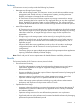
Displaying Detailed Information about a Pair of Data Volumes Use the Detailed Information window to view detailed information about a pair of data volumes. To view detailed information about a pair of data volumes, follow the procedure described in this section. The primary storage system administrator and the secondary storage system administrator can perform this operation. 1. Ensure that the Pair Operation window is open (see “Pair Operation Window” (page 121)). 2.
The Detailed Information window shows the following: • Status: The status of the pair. If the pair is split (or suspended), Status also shows the suspend type. If the pair is waiting for initial copy, Status also shows the word (Queuing).
◦ If the volume is a volume of an XP12000/XP10000 Disk Array, 00 appears for the LDKC number. ◦ If there is no volume in the local storage system, the port ID, GID, and LUN of the volume that you specified in the remote storage system when creating the pair appears. If you change or delete the port ID, GID, or LUN of the volume in the remote storage system, incorrect information appears.
• Refresh the Pair Operation window after this window is closed: If this check box is selected, the Pair Operation window updates when the Detailed Information window closes. • Previous and Next: Clicking Previous shows the pair status information for the previous pair in the list (the pair in the row above). Clicking Next shows the pair status information for the next pair in the list (the pair in the row below). The list shows a maximum of 1,024 rows at once.
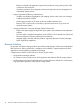
The Change Pair Option window provides the following items that can be configured: • Error Level: Specify the range used for splitting a pair when a failure occurs. ◦ Group: If a failure occurs with a pair, all pairs in the consistency group where the pair belongs are split. ◦ LU: If a failure occurs with a pair, only the pair is split. When the Change Pair Option window opens, the current option appears.
Figure 83 Pairsplit-r Window The Pairsplit-r window shows the following: • • S-VOL Write: Specify whether to permit hosts to write data to the secondary data volume. The default is Disable (that is, do not permit). ◦ Disable: Hosts cannot write data to the secondary data volume while the pair is split. ◦ Enable: Hosts can write data to the secondary data volume while the pair is split. This option is available only when the selected volume is a primary data volume. Range: Specify the split range.
• Set: Applies the settings to the Preview list in the Pair Operation window (“Pair Operation Window” (page 122)). • Cancel: Discards the settings and closes the window. Restoring a Pair of Data Volumes (Pairresync) Use the Pairresync window (“Pairresync Window” (page 192)) to restore a pair that has been split. In addition, the window allows you to recover a mirror and start data copying of an XP Continuous Access Journal pair in HOLD or HOLDING status in order to perform the delta resync operation.
Information window (see “Displaying Detailed Information about a Pair of Data Volumes” (page 185)) to monitor the detailed status of each pair. Figure 84 Pairresync Window The Pairresync window shows the following: • Range: Specify the restore range. The default is LU if two or more pairs in the same consistency group are selected; the default is Group if not. The default setting is Group when the pair status is HOLD, HOLDING, or HLDE, and in that case, you cannot change the default setting.
• • Resync Mode: Indicates the processing after recovery of the pairs. ◦ Normal: Split pair whose status is PSUS or PSUE is recovered. ◦ Delta: The delta resync operation is performed. For information about the requirements to perform the delta resync operation, see “Requirements for Performing the Delta Resync Operation” (page 89). ◦ Return to standby: The status of the pairs is recovered from HLDE to HOLD. Error Level: Specify the range used for splitting a pair when a failure occurs.
To restore a pair that was released from the secondary storage system, first release the pair from the primary storage system, and then restore the pair using the appropriate initial copy option. Note: If a pair deletion is performed, it is possible that the deletion takes effect on the secondary data volume later than it takes effect on the primary data volume. Therefore, an error may occur if you reference the status of a pair or manipulate a pair immediately after the pair is deleted by RAID Manager.
waiting for device-end from a primary storage system that cannot communicate with its the secondary storage system, thus allowing host operations to continue. If you specify Force when the pair status is other than SMPL, Range is set to Group. ◦ Normal: The pairs are released only if the primary storage system is able to change the pair status of the primary and secondary data volumes to SMPL.
If a pinned track occurs on an XP Continuous Access Journal secondary data volume that is in the 2DC configuration (that is, XP Continuous Access Journal and XP Continuous Access Synchronous with the system option mode 707), use the following procedure: 1. Connect to the XP Continuous Access Synchronous primary storage system (primary site). 2.
8 Usage Monitor Operations This chapter describes using the Usage Monitor window to follow the collection and display of performance monitoring statistics.
3. In the Display Item window (see “Display Item Window” (page 199)), select an appropriate option in Select Volume: • To view I/O statistics for all LDEVs to be monitored in the storage system, select All Volumes. • To view I/O statistics for a specific journal group, select JNL Group, and then enter a journal group number (00-FF). If you specify an unused journal group, the graph is not available.
Figure 86 Display Item Window Table 36 Remote Copy I/O Statistics Statistic Description Host I/O Write Record Count The number of write I/Os per second. Write Transfer Rate The amount of data that is written per second. The unit is kilobytes per second. Initial Copy Initial Copy Hit Rate The initial copy hit rate. The unit is percent. Average Transfer Rate The average transfer rate for initial copy operations. The unit is kilobytes per second.
Table 36 Remote Copy I/O Statistics (continued) Statistic Description M-JNL Total Number of Journal The number of journals at the primary storage system. M-JNL Average Transfer Rate The average transfer rate for journals in the primary storage system. The unit is kilobytes per second. M-JNL Average RIO Response The remote I/O process time on the primary storage system. The unit is milliseconds.
Table 38 I/O Stats in Asynchronous Copy and R-JNL When Journal Group Attribute is Master/Restore. Statistic Description Asynchronous Copy R JNL Asynchronous RIO count The number of asynchronous remote I/Os per second at the secondary storage system. R JNL Total Number of Journal The number of journals at the secondary storage system. R JNL Average Transfer Rate The average transfer rate for journals in the secondary storage system. The unit is kilobytes per second.
(1) Date and time when the operation finished (2) Time taken for copying (from the start to the end of copying). This is displayed only when the operation (see 7) is Paircreate Complete or Pairresync Complete.
9 Performing Disaster Recovery Operations This chapter describes how to determine the best approach for disaster recovery. The user should anticipate and plan for all types of failures and disasters.
XP Continuous Access Journal pairs enables your business tasks to be taken over to the secondary site, using secondary data volumes in the secondary site. • The horctakeover command checks the pair status of secondary data volumes and splits journal groups that will become an XP Continuous Access Journal pair. This ensures consistency of secondary data volumes and makes the secondary data volumes usable.
Resuming Normal Operations at the Primary Site Once the XP Continuous Access Journal volume pairs have been established in the reverse direction, you are ready to resume normal operations at the primary site. The following procedure explains how to resume normal operations at the primary site by using RAID Manager.
4. 5. (page 207), or if the primary/secondary relationship of the XP Continuous Access Journal pair is reversed (when the copy direction is reversed as illustrated in the upper-right figure in “Recovery from Failure in the Primary Site (When Delta Resync Operation is Performed)” (page 207)), use RAID Manager to perform delta resync operation (pairresync –swaps) on the XP Continuous Access Journal pair for delta resync operation in the XP Continuous Access Journal secondary site.
Figure 87 Recovery from Failure in the Primary Site (When Delta Resync Operation is Performed) Recovering from Primary Site Failures in XP Continuous Access Journal 3DC Cascading configuration If a disaster or failure occurs in the primary site in a 3DC cascading configuration combining XP Continuous Access Journal sites, you can use XP Continuous Access Journal primary data volumes in the intermediate site to enable the intermediate site to take over your business tasks.
Figure 88 Transferring Operations to the Intermediate Site from the Primary Site in the Case of Failure For detailed information about how to use RAID Manager, see the HP RAID Manager User Guide. When a disaster or failure occurs, the above procedure allows you to resume your business tasks by using the XP Continuous Access Journal pair volume in the intermediate site.
Figure 89 Transferring Operations to the Primary Site in the Case of Failure in the Intermediate Site Recovering from a Failure by Duplicating Volumes in a 3DC Cascading Configuration In the 3DC cascading configuration that consists of three Continuous Access Journal sites, if a failure occures between the primary site and the intermediate site of the Continuous Access Journal pair, the status of journal groups in the primary site and the intermediate site might remain Stopping (the pair status is Suspendi
1. 2. 3. Check the consistency of the XP Continuous Access Synchronous S-VOL in the intermediate site. Use RAID Manager to execute the horctakeover command on the XP Continuous Access Synchronous pair that exists between the primary site and the intermediate site. Wait until the XP Continuous Access Synchronous S-VOL in the intermediate site becomes suspended (in SSWS status) or changes to an XP Continuous Access Synchronous P-VOL.
Notes: • If you followed step a above, remove failures in the primary site and other locations, change the system to a 3DC multi-target configuration (see “Changing to a 3DC Multi-Target Configuration After Recovering from Primary Site Failures” (page 93)), and then follow the instructions in “Transferring Business Tasks from the XP Continuous Access Secondary Site to the Primary Site (in a 3DC Multi-target Configuration)” (page 94) in order to transfer the business tasks back to the primary site.
3. 4. Check the execution result of the horctakeover command. When the primary/secondary relationship of the XP Continuous Access Synchronous pair is not reversed (meaning that the copy direction is not reversed as illustrated in Figure 91 (page 213)), or when the primary/secondary relationship of the XP Continuous Access Synchronous pair is reversed (when the copy direction is reversed as illustrated in Figure 91 (page 213).
Figure 91 Recovery from a Disaster in the Primary Site (When Delta Resync Operation Is Performed) Recovering from a Disaster in a 2DC Configuration of XP Continuous Access Journal and XP Continuous Access Synchronous If a disaster or a failure occurs on the primary site, which is part of the 2DC configuration by using XP Continuous Access Journal and XP Continuous Access Synchronous with the system option mode 707, you can continue your business tasks by using the XP Continuous Access Journal secondary vol
4. 5. Confirm that the XP Continuous Access Journal S-VOL has changed to SMPL status. When the XP Continuous Access Journal S-VOL status changes to SMPL, use that volume and resume the business tasks on the remote site. Note: Unlike the 3DC cascading configuration, the 2DC configuration does not allow you to continue your business tasks on the intermediate site.
Recovering the Primary Site from a Failure When the System Consists of Multiple Primary and Secondary Storage Systems If a disaster or a failure occurs on the primary site, where the system consists of multiple primary and secondary storage systems, you can continue the business tasks in the remote site and maintain the data consistency in the consistency group. If a disaster or a failure occurs on the primary site, first transfer the tasks from the primary to the secondary site.
10 Troubleshooting This chapter describes general troubleshooting errors and corrective actions: • “General Troubleshooting” (page 216) • “Checking XP Continuous Access Journal Error Codes” (page 221) • “Checking Service Information Messages (SIMs)” (page 238) • “Troubleshooting When Using RAID Manager” (page 221) • “Calling HP Technical Support” (page 240) General Troubleshooting Table 41 (page 216) provides general troubleshooting information for XP Continuous Access Journal.
Table 41 General Troubleshooting Information for XP Continuous Access Journal (continued) Error Corrective Action The pair status is suspended. Check the pair status in the Detailed Information window, and see “Troubleshooting Suspended XP Continuous Access Journal Pairs” (page 219). Paircreate or pairresync operation resulted in If the timeout error was caused by a hardware failure, a SIM a timeout error. is generated.
Table 42 Troubleshooting Problems with the Status of Logical Paths (continued) Path Status Description Corrective Action If necessary, connect to the remote storage system to delete the paths or remote storage systems and reconfigure the ports, then reconnect to the local storage system. After that, add the path and remote storage system again. Serial Number Mismatch The serial number (S/N) of the remote storage system does not match the specified serial number (S/N).
Table 42 Troubleshooting Problems with the Status of Logical Paths (continued) Path Status Description Corrective Action Delete DKC command, and then add the path and the remote storage system again by using the Add Path or Add DKC command. A failure occurs in the path relay equipment. Repair the path relay equipment. After that, delete the path by using the Delete Path or Delete DKC command, and then add the path and the remote storage system again by using the Add Path or Add DKC command.
Table 43 Troubleshooting Suspended XP Continuous Access Journal Pairs (continued) Suspend Type Applies To Description Corrective Action volume, secondary data volume nonvolatile memory during the IMPL procedure. This error occurs only if the primary storage system is without power for more than 48 hours (power failure and fully discharged batteries).
Table 44 Resolving XP Continuous Access Journal Pair Suspension (continued) Classification Causes of Suspension SIM Recovery Procedure systems, the parity groups for journal volumes). Restore the failed pairs (Pairresync). RIO overload or RIO failure An unrecoverable RIO (remote I/O) DC2x timeout occurred because the storage system or network relay devices were overloaded. Or, the RIO could not be finished due to a failure in the storage system. Release the failed pairs (pairsplit-S).
a. Find the error code from the logs displayed on the RAID Manager window. Figure 93 (page 222) shows an example of a log displayed on the RAID Manager window. Figure 93 Example of a Log Displayed on the RAID Manager Window Error codes appear on the right of SSB=. The alphanumeric characters of last the four digits on the left of the comma(,) indicates SSB1 (for example, B9E1), and the alphanumeric characters of the last four digits on the right of the comma (,) indicates SSB2 (for example, B901). b.
Table 45 Error Codes and Error Contents When Operating RAID Manager (continued) Error Code (SSB1) Error Code (SSB2) Error Contents 3708 The XP Continuous Access Journal pair cannot be created because the specified P-VOL was being shredded. 3709 A request of XP Continuous Access Journal Paircreate (journal suspend mode) or XP Continuous Access Journal Pairresync (journal resync mode) was received. However, the command was rejected because the specifying of the restore journal group was incorrect.
Table 45 Error Codes and Error Contents When Operating RAID Manager (continued) Error Code (SSB1) Error Code (SSB2) Error Contents 3737 In the configuration where three XP Continuous Access Journal sites are combined, because the pair status of another mirror is not fixed, the XP Continuous Access Journal pair cannot be created. 3738 A request of XP Continuous Access Journal Paircreate was received.
Table 45 Error Codes and Error Contents When Operating RAID Manager (continued) Error Code (SSB1) Error Code (SSB2) Error Contents 8C13 Paircreate or Pairresync is not available, because the specified journal group is dedicated to the Continuous Access Journal combination (2DC), and the MU# is 0. 8F00 A request of XP Continuous Access Journal Paircreate was received. However, the command was rejected because the specified volume is an external volume.
Table 45 Error Codes and Error Contents When Operating RAID Manager (continued) Error Code (SSB1) Error Code (SSB2) Error Contents 8F28 A request of XP Continuous Access Journal Paircreate or Pairresync was received. However, the command was rejected because it could not access the specified P-VOL or S-VOL. 8F29 A request of XP Continuous Access Journal Paircreate was received. However, the command was rejected because the specified master journal group was unusable.
Table 45 Error Codes and Error Contents When Operating RAID Manager (continued) Error Code (SSB1) Error Code (SSB2) Error Contents 8F67 A request of XP Continuous Access Journal Paircreate was received. However, the command was rejected because the specified secondary storage system did not support the external volume. 8F6D A request of XP Continuous Access Journal Paircreate was received. However, the command was rejected because the specified volume was a command device.
Table 45 Error Codes and Error Contents When Operating RAID Manager (continued) Error Code (SSB1) Error Code (SSB2) Error Contents SMPL when the Paircreate was requested, or other than PSUS when the Pairresync was requested.) 228 Troubleshooting DB03 A request of XP Continuous Access Journal Pair status transition was received. However, the command was rejected because the pair was in the state of Suspending or Deleting.
Table 45 Error Codes and Error Contents When Operating RAID Manager (continued) Error Code (SSB1) Error Code (SSB2) Error Contents E87B A request of XP Continuous Access Journal Paircreate was received. However, the command was rejected because the specified journal group was unregistered. E87C Journal volume is not registered in the specified journal group. E87D A request of XP Continuous Access Journal Pairresync was received.
Table 45 Error Codes and Error Contents When Operating RAID Manager (continued) Error Code (SSB1) 230 Troubleshooting Error Code (SSB2) Error Contents E89A A request of XP Continuous Access Journal Paircreate was received. However, the command was rejected because the path between the storage devices for the both-way was not defined. Check whether the bidirectional normal path was defined or not. E89B A request of XP Continuous Access Journal Paircreate was received.
Table 45 Error Codes and Error Contents When Operating RAID Manager (continued) Error Code (SSB1) Error Code (SSB2) Error Contents EA0A A request of XP Continuous Access Journal Paircreate was received. However, the command was rejected because the state of restore journal group was invalid. EA12 A request of XP Continuous Access Journal Pairresync (Reverse mode) was received. However, the command was rejected because the specified S-VOL was not in SSWS status.
Table 45 Error Codes and Error Contents When Operating RAID Manager (continued) Error Code (SSB1) 232 Troubleshooting Error Code (SSB2) Error Contents EA3A A request of XP Continuous Access Journal delete pair was received. However, the command was rejected because the specified S-VOL was in the state of Transition. EA3B A request of XP Continuous Access Journal suspend pair (Reverse mode) was received. However, the command was rejected because the specified S-VOL was in the state of Suspending.
Table 45 Error Codes and Error Contents When Operating RAID Manager (continued) Error Code (SSB1) Error Code (SSB2) Error Contents Continuous Access Asynchronous. Check the license capacity as well as the related program product. EAA5 A request of XP Continuous Access Journal Paircreate was received. However, the command was rejected because the desired capacity exceeded the charging capacity of the secondary storage system’s XP Continuous Access Journal.
Table 45 Error Codes and Error Contents When Operating RAID Manager (continued) Error Code (SSB1) Error Code (SSB2) Error Contents EB29 A request to configure the system that consists of multiple primary and secondary storage systems was received. However, the command was rejected because the delta resync settings are configured to the primary and secondary storage systems. EB2F A request of XP Continuous Access Journal Paircreate for delta resync operation was received.
Table 45 Error Codes and Error Contents When Operating RAID Manager (continued) Error Code (SSB1) Error Code (SSB2) Error Contents EB5E A request of XP Continuous Access Journal Paircreate was received. However, the command was rejected because the state of S-VOL was not SMPL. EB5F A request of XP Continuous Access Journal Paircreate was received. However, the command was rejected because the program product of XP Continuous Access Journal was not installed in the secondary storage system.
Table 45 Error Codes and Error Contents When Operating RAID Manager (continued) Error Code (SSB1) Error Code (SSB2) EB7E Error Contents The XP Continuous Access Journal pair cannot be created because the specified S-VOL is in the either one of following two statuses: • The specified S-VOL is being used for the XP Business Copy pair. • The specified S-VOL is the reserved volume. EB7F A request of Paircreate was received.
Table 45 Error Codes and Error Contents When Operating RAID Manager (continued) Error Code (SSB1) Error Code (SSB2) Error Contents EBCA A request for XP Continuous Access Journal Pairresync (journal resync mode) was received. However, the command was rejected because the journal restore operation is in progress in the XP Continuous Access Journal pair having another mirror ID.
Table 45 Error Codes and Error Contents When Operating RAID Manager (continued) Error Code (SSB1) Error Code (SSB2) Error Contents EBE5 A request of XP Continuous Access Journal Paircreate or Pairresync was received. However, the command was rejected because the journal volume of the specified restore journal group was blocked. EBFD A request of XP Continuous Access Journal Paircreate was received. However, the command was rejected because the specified restore journal group was not registered.
Table 46 Typical SIMs Showing the Reference Code and SIM Type Reference Code Severity Description SIM Generated By Byte 22 Byte 23 SVP Log File 21 80 Moderate Logical path is blocked due to a failure. Primary/secondary SIM Log storage system 21 81 Service Logical path is restored. Primary/secondary SSB Log storage system 21 82 Moderate Line failure is reported by the extender.
Calling HP Technical Support If you need to call HP technical support, make sure to provide as much information about the problem as possible, including: • The circumstances surrounding the error or failure • The exact content of any error messages displayed on the host system(s) • The exact content of any error messages displayed by Remote Web Console • The Remote Web Console configuration information (use the FD Dump Tool) • The service information messages (SIMs), including reference codes and s
11 Support and Other Resources Related Documentation • HP RAID Manager User Guide • HP XP24000/XP20000 Data Retention Utility User Guide • HP XP24000/XP20000 LUN Expansion User Guide • HP XP24000/XP20000 Performance Monitor User Guide • HP XP24000/XP20000 Auto LUN Software User Guide • HP XP24000/XP20000 Performance Control User Guide • HP XP24000/XP20000 Business Copy Software User Guide • Hitachi ShadowImage™ for Mainframe User Guide: HP XP24000 Disk Array, HP XP20000 Disk Array • HP XP24
HP Technical Support For worldwide technical support information, see the HP support website: http://www.hp.com/support Before contacting HP, collect the following information: • Product model names and numbers • Technical support registration number (if applicable) • Product serial numbers • Error messages • Operating system type and revision level • Detailed questions Subscription Service HP recommends that you register your product at the Subscriber’s Choice for Business website: http://www.
Glossary C CU Control unit. D DC Data center. Configurations can be either 2DC (two data centers) or 3DC (one primary and two secondary data centers). DKC Disk controller. E ESCON Enterprise systems connection An optical interface used to connect the mainframe to the control unit; a predecessor to FICON. H HBA Host bus adapter. J JNL Journal. L LCP Local control port. LUN Logical unit (also called device emulation or device type). M MCU Main control unit. N NVS Nonvolatile storage.
SIM Service information message. SMPL Simplex. SSID Subsystem identifier; storage system identifier. SVP Service processor. A computer built into a disk array. The SVP, used only by an HP service representative, provides a direct interface to the disk array. sync See . V VOL, vol 244 Glossary Volume.
Index C components, 13 control units (CUs), 15 conventions storage capacity values, 241 D database recovery, 203 disaster recovery, 203 preparing for, 203 document related documentation, 241 documentation HP website, 241 providing feedback, 242 F file recovery, 203 H help obtaining, 242 HP technical support, 242 N no volumes, 91 P pinned track, 195, 196 point-in-time copy (PiT), 195 power off/on requirements, 155 primary site update, 90 R read and write I/O operations, 23 related documentation, 241 S