Hardware Reference Guide OMEN X
© Copyright 2016 HP Development Company, L.P. Bluetooth is a trademark owned by its proprietor and used by HP Inc. under license. The information contained herein is subject to change without notice. The only warranties for HP products and services are set forth in the express warranty statements accompanying such products and services. Nothing herein should be construed as constituting an additional warranty. HP shall not be liable for technical or editorial errors or omissions contained herein.
About this book WARNING! Indicates a hazardous situation that, if not avoided, could result in death or serious injury. CAUTION: Indicates a hazardous situation that, if not avoided, could result in minor or moderate injury. IMPORTANT: Indicates information considered important but not hazard-related. A notice alerts the user that failure to follow a procedure exactly as described could result in loss of data or in damage to hardware or software.
iv About this book
Table of contents 1 Product features ........................................................................................................................................... 1 Front ....................................................................................................................................................................... 2 Color zones ..........................................................................................................................................
Appendix C Accessibility ................................................................................................................................. 37 Supported assistive technologies ....................................................................................................................... 37 Contacting support .............................................................................................................................................. 37 Index ...........................
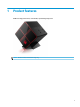
1 Product features OMEN X is a high performance, customizable, expandable gaming tower. NOTE: Product colors and features may vary.
Front Component Description (1) Create unique lighting effects on the computer. Lighted color zones NOTE: See Color zones on page 3 for more information. (2) Vents (2) Enable airflow to cool internal components. NOTE: The computer fan starts up automatically to cool internal components and prevent overheating. It is normal for the internal fan to cycle on and off during routine operation.
Color zones The computer includes nine programmable lighted color zones that allow you to create unique lighting effects. With OMEN Control, you can customize the colors of each zone or group of zones. NOTE: When you first set up your computer, all of the color zones are red. There are four color effects that you can customize in OMEN Control: ● Steady color—Customize the brightness and color of the lighting for each of the nine color zones.
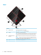
Right Component (1) Description Power button ● When the computer is off, press the button to turn on the computer. ● When the computer is on, press the button briefly to initiate Sleep. ● When the computer is in the Sleep state, press the button briefly to exit Sleep. ● When the computer is in Hibernation, press the button briefly to exit Hibernation. CAUTION: Pressing and holding down the power button results in the loss of unsaved information.
Component (3) Description Wireless light ● On: An integrated wireless device, such as a wireless local area network (WLAN) device and/or a Bluetooth® device, is on. ● Off: All integrated wireless devices are off. NOTE: On some products, the wireless light is amber when all wireless devices are off. (4) Audio-in (microphone) jack Connects an optional computer headset microphone, stereo array microphone, or monaural microphone.
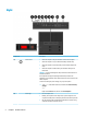
Back Component (1) Description Side panel release latch Releases the side panel. WARNING! To reduce the risk of serious injury or damage to the equipment, do not open the chassis cover of any computer containing a 1300 W PSU. To determine if you have a 600 W or 1300 W PSU, refer to the label on the back of the computer. (2) Security cable slot Attaches an optional security cable to the computer.
Component (8) Description Audio-out (headphone) jack Connects optional powered stereo speakers, headphones, earbuds, a headset, or a television audio cable. WARNING! To reduce the risk of personal injury, adjust the volume before using headphones, earbuds, or a headset. For additional safety information, see the Regulatory, Safety and Environmental Notices. To access this guide: ▲ Select the Start button, select All apps, select HP Help and Support, and then select HP Documentation.
2 Hardware upgrades Warnings and cautions Before performing upgrades, be sure to carefully read all of the applicable instructions, cautions, and warnings. WARNING! To reduce the risk of personal injury from electric shock, hot surfaces, or fire: Unplug the power cord from the AC outlet and allow the internal system components to cool before you touch them. Do not disable the power cord grounding plug. The grounding plug is an important safety feature.
Accessing the tool kit The tool kit contains the following: ● Hard drive/power supply tool ● Screwdriver/wrench, one side Phillips, one side hex. Hex screws are used on the graphics card and system fans (radiators) ● Screws Pull the logo cover away from the case (1), and then disconnect the cable from the case (2). The tool kit is located under the logo cover (3).
Replacing or installing drives The case offers four hard drive bays. The case supports three different drive types: ● 3.5 inch hard drive ● 2.5-inch solid-state drive ● U.2 drive NOTE: U.2 hard drives can be installed only in the upper-right drive bay. Installing a drive 10 1. Prepare the computer for disassembly (Preparing for disassembly on page 8). 2. Pull up on the right side of the hard drive door, and then rotate the door to the left. Note that the door remains connected to the case.
3. Slide the drive cage latch to the left (1), and then use the pull tab to pull the drive cage out of the case (2). 4. All drives must be secured into the drive cage using screws. Screw locations are as follows: (1) 3.5-inch hard drive and U.2 drive (2) 2.5-inch solid-state drive NOTE: Before installing a U.2 drive into the drive cage, you must first install the drive into a drive adapter bracket. 5. To install a drive into the drive cage: a. 3.
b. 12 2.5-inch solid-state drive: Insert the drive into the drive cage (1), and then install four mounting screws (2).
c. 6. U.2 drive: Insert the drive into the adapter bracket and secure with four screws (1). Insert the adapter bracket assembly into the drive cage (2), and then install four mounting screws (3). Insert the drive cage into the drive bay (1), and then slide the drive cage latch to the right to secure the drive cage (2).
7. Rotate the hard drive door to the right and press down until it snaps into place. Removing a drive IMPORTANT: Before you remove a hard drive, be sure to back up the data from the hard drive so that you can transfer the data to the new hard drive. 14 1. Prepare the computer for disassembly (Preparing for disassembly on page 8). 2. Pull up on the right side of the hard drive door, and then rotate the door to the left. Note that the door remains connected to the case.
3. Slide the drive cage latch to the left (1), and then use the pull tab to pull the drive cage out of the case (2). 4. To remove a drive from the drive cage: a. 3.5-inch hard drive: Remove the four mounting screws (1) from the sides of the cage, and then lift the drive out of the cage (2).
16 b. 2.5-inch solid-state drive: Remove the four mounting screws from the bottom of the cage (1) and then lift the drive out of the cage (2). c. U.2 drive: Remove the four mounting screws that secure the drive adapter bracket to the drive cage (1). Lift the adapter bracket out of the drive cage (2), and remove the four screws that secure the drive to the adapter bracket (3). Then remove the drive from the adapter bracket.
Drive security You can insert the hard drive pull tab into the drive cage to prevent unauthorized removal of the drive. 1. Pull up on the right side of the hard drive door, and then rotate the door to the left. Note that the door remains connected to the case. 2. From the outside of the drive cage, insert the pull tab into the drive cage until it is not accessible from the outside of the drive cage. 3.
Removing and replacing the access panel To access internal components, you must remove the access panel: 1. Prepare the computer for disassembly (Preparing for disassembly on page 8). 2. If a Phillips screw is installed to lock the access panel, remove the screw (1). 3. Press the release button (2), and then rotate the access panel off the computer (3). To replace the access panel, reverse the removal procedures.
Installing system memory The computer uses double data rate 4 synchronous dynamic random access memory (DDR4-SDRAM) dual inline memory modules (DIMMs). There are four memory sockets on the system board that can be populated with up to 32 GB of memory. For proper system operation, the DIMMs must be 1.
● The system will operate in flex mode if the memory capacity of the DIMM in Channel A is not equal to the memory capacity of the DIMM in Channel B. In flex mode, the channel populated with the least amount of memory describes the total amount of memory assigned to dual channel and the remainder is assigned to single channel. If one channel will have more memory than the other, the larger amount should be assigned to channel A.
4. Insert the memory module into the socket so that the latches lock it in place. NOTE: A memory module can be installed in only one way. Match the notch on the module with the tab on the memory socket. 5. Replace the access panel. 6. Reconnect the power cord and any external devices, and then turn on the computer. The computer automatically recognizes the additional memory.
Installing and removing an optical drive The computer supports only ultra slim 9.5 mm SATA optical drives. Installing an optical drive 22 1. Prepare the computer for disassembly (Preparing for disassembly on page 8). 2. Install the bezel onto the front of the optical drive. 3. Align the two small pins on the release latch with the small holes on the side of the drive, and then press the latch firmly onto the drive. 4. Insert the optical drive into the case until it snaps into place.
Removing an optical drive 1. Prepare the computer for disassembly (Preparing for disassembly on page 8). 2. Remove the access panel (Removing and replacing the access panel on page 18). 3. Eject the optical drive tray by inserting a paper clip into the hole in the optical drive and pressing inward. 4. On the outside of the computer case, insert a screwdriver into the right side of the release latch, and press the latch toward the left (1). Maintain pressure while performing the next step. 5.
Installing graphics cards You can install multiple graphics cards and associated fans. 1. Prepare the computer for disassembly (Preparing for disassembly on page 8). 2. Remove the access panel (Removing and replacing the access panel on page 18). 3. To install a graphics card: 4. 24 a. Locate the a vacant expansion socket on the system board and the corresponding expansion slot on the back of the case. b.
5. a. Remove the cover from the location where you will install the graphics card fan. b. From the inside of the case, insert the fan into place on the outer wall (1). c. From the outside of the case, install four screws (2) with the screwdriver/wrench from the tool kit (Accessing the tool kit on page 9). d. Replace the cover (3). Replace the access panel.
Removing the PCI fan The PCI fan is secured to the front of the case and provides additional cooling for the graphics cards. You must remove the entire front bezel before you can remove or install the PCI fan. 26 1. Prepare the computer for disassembly (Preparing for disassembly on page 8). 2. Remove the access panel (Removing and replacing the access panel on page 18). 3. To remove the front bezel: a.
c. Lift the fan out of the case (3). To replace the PCI fan, reverse the removal procedures.
Installing a system board The system board is secured to a system board tray. You must remove the tray before you can remove or install a system board. 28 1. Prepare the computer for disassembly (Preparing for disassembly on page 8). 2. Remove the access panel (Removing and replacing the access panel on page 18). 3. To remove the system board tray, remove the three screws that secure the tray to the case (1), slide the tray to the right (2), and then lift the tray out of the case (3). 4.
Removing the hard drive fan The hard drive fan is secured to the rear of the case under the system board tray. You must remove the tray before you can remove or install the hard drive fan. 1. Prepare the computer for disassembly (Preparing for disassembly on page 8). 2. Remove the access panel (Removing and replacing the access panel on page 18). 3. Remove the system board tray (Installing a system board on page 28). 4. To remove the rear bezel: 5. a.
Installing a power supply The computer supports power supplies that follow the ATX standard with a maximum of 1450 W. CAUTION: To prevent damage, the overall power consumption of the computer must not exceed the maximum rating of the computer power supply. 1. Prepare the computer for disassembly (Preparing for disassembly on page 8). 2. Remove the access panel (Removing and replacing the access panel on page 18). 3. Remove the system board tray (Installing a system board on page 28). 4.
7. Install three screws to secure the power supply to the case (2). NOTE: You will install one other screw in the next step to secure the grounding wire. 8. To install the power supply connector cable into the case: a. Place the connector into the corner of the power supply bay (1). b. Install the connector hex screw (2) using the wrench/screwdriver from the tool kit. c. Install the green ground wire onto the remaining power supply screw (3). d. Plug the cable into the power supply (4).
9. Connect the power supply SATA cables (1) and I/O board and cable (2). Six SATA power cables (four hard drive + one U.2 drive + one optical drive) and one PATA power connector (from the I/O board) are available to connect to the power supply. The cables in the computer case are labeled to indicate components they connect to. CAUTION: To avoid damaging the cable, pull the tab or connector instead of the cable itself. 10. Replace the power supply cover. 11. Replace the system board tray assembly.
Installing a radiator bracket for liquid cooling The radiator bracket can accommodate only 240 mm radiators. 1. Prepare the computer for disassembly (Preparing for disassembly on page 8). 2. Remove the access panel (Removing and replacing the access panel on page 18). 3. Remove any fans mounted to the side of the case. 4. If you want to add additional liquid cooling, install the radiator bracket in one of the positions shown in the following image.
6. Install the eight hex screws using the wrench/screwdriver from the tool kit (Accessing the tool kit on page 9) to secure the bracket to the case. 7. Install any needed fans. Cleaning filters 34 1. Prepare the computer for disassembly (Preparing for disassembly on page 8). 2. Remove the access panel (Removing and replacing the access panel on page 18). 3. Remove and clean the air filters on all vented sides of the computer.
A Electrostatic discharge A discharge of static electricity from a finger or other conductor may damage system boards or other staticsensitive devices. This type of damage may reduce the life expectancy of the device. Preventing electrostatic damage To prevent electrostatic damage, observe the following precautions: ● Avoid hand contact by transporting and storing products in static-safe containers. ● Keep electrostatic-sensitive parts in their containers until they arrive at static-free workstations.
B Computer operating guidelines and routine care Follow these guidelines to properly set up and care for the computer and monitor: 36 ● Keep the computer away from excessive moisture, direct sunlight, and extremes of heat and cold. ● Operate the computer on a sturdy, level surface. Leave a 10.2 cm (4-inch) clearance on all vented sides of the computer and above the monitor to permit the required airflow. ● Never restrict the airflow into the computer by blocking any vents or air intakes.
C Accessibility HP designs, produces, and markets products and services that can be used by everyone, including people with disabilities, either on a stand-alone basis or with appropriate assistive devices. Supported assistive technologies HP products support a wide variety of operating system assistive technologies and can be configured to work with additional assistive technologies. Use the Search feature on your device to locate more information about assistive features.
Index A access panel removal 18 accessibility 37 accessing the tool kit 9 audio-in (microphone) jack 5 audio-out (headphone) jacks 7 audio-out (headphone)/audio-in (microphone) jack, identifying 5 B buttons power 4 C color zones 3 color zones, identifying 2 components back 6 bottom 7 right 4 computer operating guidelines connector, power 7 D drive cage latch, identifying 36 5 E electrostatic discharge, preventing damage 35 F filters removing and cleaning G graphics cards installing 24 H hard drive inst
solid-state drive removal 14 stand 2 system board installing 28 T tool kit location 9 tool kit, identifying 2 U USB 3.0 charging (powered) port, identifying 5 USB 3.