Maintenance and Service Guide HP EliteDesk 705 G3 Small Form Factor
© Copyright 2016 HP Development Company, L.P. AMD is a trademark of Advanced Micro Devices, Inc. Bluetooth is a trademark owned by its proprietor and used by HP Inc. under license. Windows is either a registered trademark or trademark of Microsoft Corporation in the United States and/or other countries. The information contained herein is subject to change without notice.
Safety warning notice WARNING! To reduce the possibility of heat-related injuries or of overheating the device, do not place the device directly on your lap or obstruct the device air vents. Use the device only on a hard, flat surface. Do not allow another hard surface, such as an adjoining optional printer, or a soft surface, such as pillows or rugs or clothing, to block airflow. Also, do not allow the AC adapter to contact the skin or a soft surface, such as pillows or rugs or clothing, during operation.
iv Safety warning notice
Table of contents 1 Product features ........................................................................................................................................... 1 Standard configuration features ........................................................................................................................... 1 Front panel components ........................................................................................................................................
4 Removal and replacement procedures – small form factor (SFF) chassis .......................................................... 18 Preparation for disassembly ............................................................................................................................... 18 Access panel ......................................................................................................................................................... 19 Front bezel ......................................
Computer Setup–Main ....................................................................................................................... 68 Computer Setup—Security ............................................................................................................... 70 Computer Setup—Advanced ............................................................................................................. 72 Recovering the Configuration Settings .......................................................
10 System backup and recovery ..................................................................................................................... 121 Backing up, restoring, and recovering in Windows 10 ...................................................................................... 121 Creating recovery media and backups ............................................................................................ 121 Creating HP Recovery media (select products only) ..................................
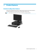
1 Product features Standard configuration features Features may vary depending on the model. For support assistance and to learn more about the hardware and software installed on your computer model, run the HP Support Assistant utility. NOTE: This computer model can be used in a tower orientation or a desktop orientation.
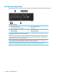
Front panel components Drive configuration may vary by model. Some models have a bezel blank covering the slim optical drive bay. Front panel components 1 Slim optical drive (optional) 6 Audio-out (headphone) jack 2 USB 2.0 charging (powered) port (black) 7 Power button 3 USB 2.0 port (black) 8 Hard drive activity light 4 USB 3.
Rear panel components Rear panel components 1 PS/2 mouse connector (green) 7 PS/2 keyboard connector (purple) 2 Serial port 8 DisplayPort monitor connectors 3 RJ-45 (network) jack 9 VGA monitor connector 4 USB 2.
Serial number location Each computer has a unique serial number and a product ID number that are located on the exterior of the computer. Keep these numbers available for use when contacting customer service for assistance.
2 Illustrated parts catalog NOTE: HP continually improves and changes product parts. For complete and current information on supported parts for your computer, go to http://partsurfer.hp.com, select your country or region, and then follow the on-screen instructions.
Item Description (1) Access panel (2) Front bezel x Bezel blank (3) System board (includes replacement thermal material) (4) Power supply 200W, 92% efficient 200W, 85% efficient 200W, standard (5) Fan sink (includes replacement thermal material) Memory modules (PC4-17000) 16-GB 8-GB 4-GB 2-GB x Processors (include replacement thermal material) AMD A12-9800, 3.8 GHz AMD A10-9700, 3.5 GHz AMD A8-9700, 3.5 GHz AMD A6-9600, 3.1 GHz AMD A12-8870, 3.7 GHz AMD A10-8770, 3.5 GHz AMD A6-8570, 3.
Misc parts Item Description (1) Fan baffle (2) Rear baffle (3) Solenoid lock (4) Front I/O assembly (5) Speaker (6) Power switch (7) SATA drive power cable (8) SATA data cable, 19.
Item Description (11) nVIDIA GT730 2 GB DDR3 PCIex8 (12) Serial port, PCI card x WLAN modules Intel Dual Band Wireless-AC 8260 + Bluetooth 4.0 Intel Dual Band Wireless-AC 3165 + Bluetooth 4.0 Intel Dual Band Wireless-AC 7265 NV x Front bezel dust filter x Chassis stand x Center strip kit x M.2 USB cable x Slim optical drive bezel blank x Slim optical drive latch x Hard drive conversion bracket, 2.5-inch to 3.
Item Description Antimicrobial (People’s Republic of China only) Washable Wireless (Brazil only) HP USB Hardened USB, gray Keyboards x USB, gray PS/2 slim Antimicrobial HP USB slim HP USB Conferencing Wireless keyboard, mouse, and dongle USB/PS2 Washable USB, Smart card x not illustrated Misc boards Description nVIDIA GT730 2 GB DDR3 PCIex8 NVIDIA NVS 310 512MB DDR3 PCI Express Gen 2 x16 DisplayPort 1.2 Multi-Display Professional Graphics Board Intel PRO/1000 NIC Printer port Serial port USB 3.
Drives Description Hard drives 2-TB, 7200-rpm 1-TB, 7200-rpm, 3.5-inch 1-TB, hybrid SSD, 5400-rpm, 2.5-inch 1-TB, hybrid SSD, 7200-rpm, 3.5-inch 500 GB, 7200 rpm, 3.5-inch 500-GB, 7200-rpm, 2.5-inch 500-GB, 7200-rpm, 2.5-inch, SED 500-GB, 5400-rpm, 2.5-inch, OPAL2, FIPS 500-GB, 5400-rpm, hybrid SSD, 2.5-inch Solid-state drives, 2.
3 Routine care, SATA drive guidelines, and disassembly preparation This chapter provides general service information for the computer. Adherence to the procedures and precautions described in this chapter is essential for proper service. CAUTION: When the computer is plugged into an AC power source, voltage is always applied to the system board. You must disconnect the power cord from the power source before opening the computer to prevent system board or component damage.
Preventing electrostatic damage to equipment Many electronic components are sensitive to ESD. Circuitry design and structure determine the degree of sensitivity. The following packaging and grounding precautions are necessary to prevent damage to electric components and accessories. ● To avoid hand contact, transport products in static-safe containers such as tubes, bags, or boxes. ● Protect all electrostatic-sensitive parts and assemblies with conductive or approved containers or packaging.
Recommended materials and equipment The following grounding equipment is recommended to prevent electrostatic damage: ● Antistatic tape ● Antistatic smocks, aprons, or sleeve protectors ● Conductive bins and other assembly or soldering aids ● Conductive foam ● Conductive tabletop workstations with ground cords of one-megohm +/- 10% resistance ● Static-dissipative table or floor mats with hard ties to ground ● Field service kits ● Static awareness labels ● Wrist straps and footwear straps pr
● Never cover the ventilation slots on the monitor with any type of material. ● Install or enable power management functions of the operating system or other software, including sleep states. Routine care General cleaning safety precautions 1. Never use solvents or flammable solutions to clean the computer. 2. Never immerse any parts in water or cleaning solutions; apply any liquids to a clean cloth and then use the cloth on the component. 3.
● If you want to remove a key, use a specially designed key puller to prevent damage to the keys. This tool is available through many electronics supply outlets. CAUTION: Never remove a wide, level key (like the space bar) from the keyboard. If these keys are improperly removed or installed, the keyboard may not function properly. ● Cleaning under a key may be done with a swab moistened with isopropyl alcohol and then squeezed out.
Cables and connectors Most cables used throughout the unit are flat, flexible cables. These cables must be handled with care to avoid damage. Apply only the tension required to seat or unseat the cables during insertion or removal from the connector. Handle cables by the connector whenever possible. In all cases, avoid bending or twisting the cables, and ensure that the cables are routed in such a way that they cannot be caught or snagged by parts being removed or replaced.
SATA hard drives Serial ATA Hard Drive Characteristics Number of pins/conductors in data cable 7/7 Number of pins in power cable 15 Maximum data cable length 39.37 in (100 cm) Data interface voltage differential 400-700 mV Drive voltages 3.3 V, 5 V, 12 V Jumpers for configuring drive N/A Data transfer rate 6.
4 Removal and replacement procedures – small form factor (SFF) chassis Adherence to the procedures and precautions described in this chapter is essential for proper service. After completing all necessary removal and replacement procedures, run the Diagnostics utility to verify that all components operate properly. NOTE: Not all features listed in this guide are available on all computers. NOTE: HP continually improves and changes product parts.
Access panel 1. Prepare the computer for disassembly (Preparation for disassembly on page 18). 2. Pull up the access panel handle (1), and then lift the panel off the computer (2). To install the access panel, reverse the removal procedure. Front bezel 1. Prepare the computer for disassembly (Preparation for disassembly on page 18). 2. Remove the access panel (Access panel on page 19). 3. Lift up the three tabs on the side of the bezel (1), and then rotate the bezel off the chassis (2).
Front bezel security The front bezel can be locked in place by installing a security screw provided by HP. To install the security screw: 20 1. Prepare the computer for disassembly (Preparation for disassembly on page 18). 2. Remove the access panel (Access panel on page 19). 3. If you do not have a 6-32 standard screw, remove one of the four silver 6-32 standard screws located on top of the drive cage.
Slim optical drive bezel blank On some models, there is a bezel blank covering the slim optical drive bay. Remove the bezel blank before installing an optical drive. To remove the bezel blank: 1. Remove the access panel (Access panel on page 19). 2. Remove the front bezel (Front bezel on page 19). 3. To remove the slim optical drive bezel blank, press inward on the three retaining tabs that hold the bezel blank in place (1), and then rotate the bezel blank off the front bezel (2).
Dust filter Some models are equipped with a front bezel that includes a dust filter. You must periodically clean the dust filter so that the dust collected on the filter does not impede air flow through the computer. NOTE: The optional dust filter front bezel is available from HP. To clean the dust filter: 22 1. Remove the access panel (Access panel on page 19). 2. Remove the front bezel (Front bezel on page 19). 3.
5. Clean dust from the filter access panel with a soft brush or cloth. If heavily soiled, rinse the filter access panel clean with water. 6. Clean the filter element with a soft brush or cloth. If heavily soiled, rinse the filter clean with water. 7. To replace the dust filter, slide the right side of the filter onto the filter access panel (1), and then press the filter onto the filter access panel (2) to secure it in place. 8.
Memory Description 16-GB, PC4-17000 8-GB, PC4-17000 4-GB, PC4-17000 2-GB, PC4-17000 The computer comes with double data rate 4 synchronous dynamic random access memory (DDR4-SDRAM) dual inline memory modules (DIMMs). DIMMs The memory sockets on the system board can be populated with up to four industry-standard DIMMs. These memory sockets are populated with at least one preinstalled DIMM.
● The system will operate in single channel mode if the DIMM sockets are populated in one channel only. ● The system will operate in a higher-performing dual channel mode if the total memory capacity of the DIMMs in Channel A is equal to the total memory capacity of the DIMMs in Channel B. The technology and device width can vary between the channels. For example, if Channel A is populated with two 1 GB DIMMs and Channel B is populated with one 2 GB DIMM, the system will operate in dual channel mode.
5. Push the module down into the socket, ensuring that the module is fully inserted and properly seated. Make sure the latches are in the closed position (3). 6. Repeat steps 4 and 5 to install any additional modules. The computer should automatically recognize the additional memory the next time you turn on the computer.
Expansion card Description nVIDIA GT730 2 GB DDR3 PCIex8 NVIDIA NVS 310 512MB DDR3 PCI Express Gen 2 x16 DisplayPort 1.2 Multi-Display Professional Graphics Board USB 3.1 Type Cx1 PCIe x1 card Printer port, PCI card Serial port, PCI card PCIe to M.2 adapter Intel PRO/1000 NIC WLAN 802.11 a/b/g/n + Bluetooth 4.0 module WLAN 802.11 (7265NV) a/b/g/n 2x2 + Bluetooth 4.0 module WLAN 802.11 (7265AN) a/b/g/n 2x2 WLAN module expansion card adapter M.
4. Release the slot cover retention latch that secures the slot covers by lifting the tab on the latch and rotating the latch to the open position. 5. Before installing an expansion card, remove the expansion slot cover or the existing expansion card. NOTE: Before removing an installed expansion card, disconnect any cables that may be attached to the expansion card. a. 28 If you are installing an expansion card in a vacant socket, remove the appropriate expansion slot cover on the back of the chassis.
b. If you are removing a PCI Express x1 card, hold the card at each end and carefully rock it back and forth until the connectors pull free from the socket. Lift the card straight up (1) then away from the inside of the chassis (2) to remove it. Be sure not to scrape the card against other components. c.
8. To install a new expansion card, hold the card just above the expansion socket on the system board then move the card toward the rear of the chassis (1) so that the bottom of the bracket on the card slides into the small slot on the chassis. Press the card straight down into the expansion socket on the system board (2). NOTE: When installing an expansion card, press firmly on the card so that the whole connector seats properly in the expansion card socket. 9.
Drives Description Hard drives 2-TB, 7200-rpm 1-TB, 7200-rpm, 3.5-inch 1-TB, hybrid SSD, 5400-rpm, 2.5-inch 1-TB, hybrid SSD, 7200-rpm, 3.5-inch 500 GB, 7200 rpm, 3.5-inch 500-GB, 7200-rpm, 2.5-inch 500-GB, 7200-rpm, 2.5-inch, SED 500-GB, 5400-rpm, 2.5-inch, OPAL2, FIPS 500-GB, 5400-rpm, hybrid SSD, 2.5-inch Solid-state drives, 2.
System board connections Refer to the following illustration and table to identify the system board connectors for your model. 32 Item System board connector System board label Color Component 1 PCI Express x16 Gen 2 downshifted to a x4 X4PCIEXP white Expansion card 2 PCI Express x1 Gen 2 X1PCIEXP2 black Expansion card 3 PCI Express x16 Gen 3 X16PCIEXP black Expansion card 4 PCI Express x1 Gen 2 X1PCIEXP1 black Expansion card 5 SATA 3.
Drive positions Drive positions 1 9.5 mm slim optical drive bay 2 3.5-inch primary hard drive bay 3 3.5-inch secondary hard drive bay 4 2.5-inch hard drive bay NOTE: The drive configuration on your computer may be different than the drive configuration shown above. To verify the type and size of the storage devices installed in the computer, run Computer Setup.
● HP has provided four extra 6-32 hard drive mounting screws installed on the top of the hard drive cage (1) for installing a hard drive into the 3.5-inch secondary hard drive bay. If you are replacing a hard drive, remove the mounting screws from the old drive and install them in the new drive. NOTE: You can also use one of the extra mounting screws to secure the front bezel (see Front bezel security on page 20 for more information).
Removing a 9.5mm slim optical drive CAUTION: All removable media should be taken out of a drive before removing the drive from the computer. 1. Prepare the computer for disassembly (Preparation for disassembly on page 18). 2. Remove the access panel (Access panel on page 19). 3.
Installing a 9.5mm slim optical drive 1. Prepare the computer for disassembly (Preparation for disassembly on page 18). 2. Remove the access panel (Access panel on page 19). 3. Remove the front bezel if you are installing a drive in a bay covered by a bezel blank, then remove the bezel blank. See Front bezel on page 19 for more information. 4. Align the small pin on the release latch with the small hole on the side of the drive and press the latch firmly onto the drive. 5.
Removing and replacing a primary 3.5-inch hard drive NOTE: Before you remove the old hard drive, be sure to back up the data from the old hard drive so that you can transfer the data to the new hard drive. 1. Prepare the computer for disassembly (Preparation for disassembly on page 18). 2. Remove the access panel (Access panel on page 19). 3. Disconnect the power cable (1) and data cable (2) from the rear of the hard drive. 4. Pull the release lever next to the rear of the hard drive outward (1).
38 5. To install a hard drive, you must transfer the mounting screws from the old hard drive to the new hard drive. 6. Align the mounting screws with the slots on the chassis drive cage, press the hard drive down into the bay, and then slide it forward until it stops and locks in place.
7. Connect the power cable (1) and data cable (2) to the rear of the hard drive. NOTE: The data cable for the primary hard drive must be connected to the dark blue connector on the system board labeled SATA0 to avoid any hard drive performance problems. Removing a secondary 3.5-inch hard drive 1. Prepare the computer for disassembly (Preparation for disassembly on page 18). 2. Remove the access panel (Access panel on page 19). 3. Rotate the drive cage to its upright position.
4. Disconnect the power cable(1) and data cable (2) from the rear of the hard drive. Press the latch on the side of the drive cage (3), and then slide the drive out of the drive bay (4). 5. If you are installing a new drive, refer to Installing a secondary 3.5-inch hard drive on page 40. If you are not installing a new drive, rotate the drive cage down and replace the access panel. Installing a secondary 3.5-inch hard drive 1.
4. Rotate the drive cage to its upright position. 5. Slide the drive into the drive bay (1), and then connect the power cable (2) and data cable (3) to the rear of the hard drive. NOTE: If the drive is a secondary hard drive, connect the other end of data cable to one of the light blue SATA connectors on the system board. If the drive is the primary hard drive, connect the other end of the data cable to the dark blue SATA connector on the system board.
6. Rotate the drive cage back down to its normal position. CAUTION: Be careful not to pinch any cables or wires when rotating the drive cage down. Removing a 2.5-inch hard drive 42 1. Prepare the computer for disassembly (Preparation for disassembly on page 18). 2. Remove the access panel (Access panel on page 19). 3. Rotate the drive cage to its upright position.
4. Disconnect the power cable (1) and data cable (2) from the back of the hard drive. 5. Pull outward on the release lever at the rear of the drive (1) then slide the drive back until it stops and pull it down and out of the drive bay (2). 6. If you are installing a new drive, refer to Installing a 2.5-inch hard drive on page 44. If you are not installing a new drive, rotate the drive cage down and replace the access panel.
Installing a 2.5-inch hard drive 1. Prepare the computer for disassembly (Preparation for disassembly on page 18). 2. Remove the access panel (Access panel on page 19). 3. Install four black and blue M3 isolation mounting guide screws (two on each side of the drive). NOTE: M3 metric isolation mounting guide screws can be purchased from HP. When replacing a drive, transfer the four mounting screws from the old drive to the new drive. 4. 44 Rotate the drive cage to its upright position.
5. Align the mounting screws on the drive with the J-slots on the sides of the drive bay. Press the drive up into the drive bay then slide it forward until it locks in place. 6. Connect the power cable (1) and data cable (2) to the back of the hard drive. NOTE: If the 2.5-inch hard drive is the primary drive, connect the other end of the data cable to the dark blue SATA connector on the system board labeled SATA0 .
7. Rotate the drive cage back down to its normal position. IMPORTANT: 46 Be careful not to pinch any cables or wires when rotating the drive cage down.
Drive power cable 1. Prepare the computer for disassembly (Preparation for disassembly on page 18). 2. Remove the access panel (Access panel on page 19). 3. Rotate the drive cage to its upright position. 4. Disconnect the cable from the system board connector labeled SATAPWR0. 5. Disconnect the cable from the hard drive and the optical drive. 6. Remove the cable from the clips on the base pan and on the drive cage, and then remove the drive power cable from the computer.
Small baffle The small baffle sits between the fan sink and the rear of the computer. 1. Prepare the computer for disassembly (Preparation for disassembly on page 18). 2. Remove the access panel (Access panel on page 19). 3. Rotate the baffle upward. 4. Pull the baffle away from the rear of the computer to disengage the clips on the baffle from the rear of the computer. To install the small baffle, reverse the removal procedure.
Fan baffle The fan baffle sits on top of the fan sink. 1. Prepare the computer for disassembly (Preparation for disassembly on page 18). 2. Remove the access panel (Access panel on page 19). 3. Rotate the small baffle upward from atop the fan baffle. 4. Remove the power cable from the clips on top of the baffle (1). 5. Remove the hood sensor cable from the clips on top of the baffle (2). 6.
Hood lock The hood lock is attached to the rear of the chassis. 1. Prepare the computer for disassembly (Preparation for disassembly on page 18). 2. Remove the access panel (Access panel on page 19). 3. On the rear of the computer, remove the security screw that secures the lock. NOTE: The security screw requires a special security wrench to remove. 4. From the inside of the computer, disconnect the cable from the system board (1), and then lift the hood lock out of the computer (2).
To replace the hood lock, reverse the removal procedures.
Front I/O assembly The front I/O assembly is attached to the front of the chassis with one screw. Push the assembly into the chassis to remove. 1. Prepare the computer for disassembly (Preparation for disassembly on page 18). 2. Remove the access panel (Access panel on page 19). 3. Remove the front bezel (Front bezel on page 19). 4. Rotate the drive cage to its upright position. 5. From the front of the computer, remove the Torx T15 screw (1) that secures the assembly to the front of the chassis.
10. Pull the front I/O assembly into the computer, and then remove it (4). To install the front I/O assembly, reverse the removal procedure. NOTE: Be sure to correctly route the cables beneath the drive cage when reinstalling the assembly. Proper cable routing prevents damage to the cables and allows the drive cage to close properly.
Power switch The power switch is attached to the left, front of the chassis. 54 1. Prepare the computer for disassembly (Preparation for disassembly on page 18). 2. Remove the access panel (Access panel on page 19). 3. Remove the front bezel (Front bezel on page 19). 4. Rotate the drive cage to its upright position. 5. Remove the cable from the clips built into the bottom of the chassis, then and disconnect the power switch cable from the system board connector labeled PB/LED.
6. From the inside of the front of the chassis, press the tab at the top of the power switch (1) and push the top of the power switch out of the chassis (2). 7. Remove the power switch assembly from the outside of the computer while pulling the cable through the hole in the front of the chassis. To install the power switch, reverse the removal procedures.
Speaker The speaker is attached to the front of the chassis under the rotating drive cage. 1. Prepare the computer for disassembly (Preparation for disassembly on page 18). 2. Remove the access panel (Access panel on page 19). 3. Remove the front bezel (Front bezel on page 19). 4. Rotate the drive cage to its upright position. 5. From the outside, front of the chassis, remove the two Torx T15 screws that secure the speaker. 6.
Fan sink CAUTION: The bond between the fan sink and the processor may be very tight. If the computer will power on, before removing the fan sink, turn on the computer until it warms the fan sink. Warming the fan sink lessens the bond between the fan sink and the processor, thereby making separating them easier. Make sure not to pull the processor out of the socket when you lift the fan sink, especially if you cannot warm the fan sink prior to removal.
CAUTION: Fan sink retaining screws should be tightened in diagonally opposite pairs (as in an X) to evenly seat the fan sink on the processor to avoid damage that could require replacing the system board. Failure to install the baffle may cause the computer to overheat. Processor Description AMD A12-9800, 3.8 GHz AMD A10-9700, 3.5 GHz AMD A8-9700, 3.5 GHz AMD A6-9600, 3.1 GHz AMD A12-8870, 3.7 GHz AMD A10-8770, 3.5 GHz AMD A6-8570, 3.5 GHz 58 1.
8. Carefully lift the processor from the socket (2). CAUTION: Do NOT handle the pins in the processor socket. These pins are very fragile and handling them could cause irreparable damage. Once pins are damaged it may be necessary to replace the system board. To replace the processor, reverse the removal procedures. NOTE: After installing a new processor onto the system board, always update the system ROM to ensure that the latest version of the BIOS is being used on the computer.
Power supply Description Power supply, 200W, 92% efficient Power supply, 200W, 85% efficient Power supply, 200W, standard WARNING! To reduce potential safety issues, only the power supply provided with the computer, a replacement power supply provided by HP, or a power supply purchased as an accessory from HP should be used with the computer. WARNING! Voltage is always present on the system board when the computer is plugged into an active AC outlet.
5. From the outside, rear of the chassis, remove the three Torx T15 that secure the power supply to the back of the chassis. 6. From the inside of the chassis, push the release lever at the front of the power supply (1), slide the power supply forward, and then remove it from the chassis (2). To install the power supply, reverse the removal procedure.
System board NOTE: All system board spare part kits include replacement thermal material. NOTE: System board appearance may vary. 1. Prepare the computer for disassembly (Preparation for disassembly on page 18). 2. Remove the access panel (Access panel on page 19). 3. Rotate the small baffle into the upright position (Small baffle on page 48). 4. Remove the fan baffle (Fan baffle on page 49). 5. Rotate the drive cage to its upright position. 6.
System board callouts Sys Bd Label color Component Sys Bd Label color Component X4PCIEXP White Expansion card DIMM3 Black Memory module X1PCIEXP2 Black Expansion card DIMM2 White Memory module X16PCIEXP Black Expansion card DIMM1 Black Memory module X1PCIEXP1 Black Expansion card PB/LED Black Front I/O/power switch PSFAN Red Chassis fan PWRCMD White Power supply HLCK Black Hood lock SATA PWR0 Black Drive power HSENSE White Hood sensor PWR White 6-pin main powe
64 Sys Bd Label color Component Sys Bd Label color Component SATA2 Light blue Any SATA Device other than the primary hard drive XBT Black RTC battery FRONT USB3 Blue Front I/O and power switch COMB Black Optional second serial port SD RDR Black Card reader PSWD Green Clear system passwords XU Black Processor CMOS Yellow Reset CMOS SATA0 Dark blue Hard drive USB C White USB C connector CPUFAN White Processor fan USB2 Yellow Front I/O SATA1 Light blue Any SATA Devi
Using the Small Form Factor Computer in a Tower Orientation The Small Form Factor computer can be used in a tower orientation. The HP logo plate on the front bezel is adjustable for either desktop or tower orientation. 1. Prepare the computer for disassembly (Preparation for disassembly on page 18). 2. Orient the computer so that its right side is facing down and place the computer in the optional stand.
5 Computer Setup (F10) Utility Computer Setup (F10) Utilities Use Computer Setup (F10) Utility to do the following: ● Change factory default settings. ● View the system configuration, including settings for processor, graphics, memory, audio, storage, communications, and input devices. ● Modify the boot order of bootable devices such as hard drives, optical drives, or USB flash media devices.
3. A choice of four headings appears in the Computer Setup Utilities menu: Main, Security, Advanced, and UEFI Drivers. NOTE: Selecting UEFI Drivers restarts the computer into the 3rd party option ROM management application. You can access this application directly by pressing F3 during startup. 4. Use the arrow (left and right) keys to select the appropriate heading. Use the arrow (up and down) keys to select the option you want, then press Enter.
Computer Setup–Main NOTE: Support for specific Computer Setup options may vary depending on the hardware configuration. Table 5-1 Computer Setup—Main Option Description System Information Lists all information in following list if Advanced System Information is selected. Lists smaller subset if Basic System Information is selected.
Table 5-1 Computer Setup—Main (continued) Option System IDs Replicated Setup Description ● Serial Number ● SKU Number ● Product Family ● System Board CT ● Product Name Lets you clear the following values: ● Asset Tracking Number ● Ownership Tag Backup current settings to USB device Saves system configuration to a formatted USB flash media device. Restore current settings from USB device Restores system configuration from a USB flash media device.
Computer Setup—Security NOTE: Support for specific Computer Setup options may vary depending on the hardware configuration.
Table 5-2 Computer Setup—Security (continued) Option Description CAUTION: Clearing the TPM resets it to factory defaults and turns it off. You will lose all created keys and data protected by those keys. Set Up BIOS Power-On Password Lets you set and enable a BIOS power-on password. The power-on password prompt appears after a power cycle or reboot. If the user does not enter the correct power-on password, the unit will not boot. Change BIOS Power-On Password Lets you change the BIOS power-on password.
Table 5-2 Computer Setup—Security (continued) Option Description Default is ‘Unlock’. Cover Removal Sensor (Disabled/Notify user/Administrator password) Lets you disable the cover sensor or configure what action is taken if the computer cover was removed. Default is ‘Disabled’. NOTE: Notify user alerts the user that the sensor has detected that the cover has been removed. Administrator Password requires that the password be entered to boot the computer if the sensor detects that the cover has been removed.
Table 5-3 Computer Setup—Advanced (for advanced users) (continued) Option Heading Specify the order in which legacy boot sources (such as a network interface card, internal hard drive, USB optical drive, or internal optical drive) are checked for a bootable operating system image. Each device on the list may be individually excluded from or included for consideration as a bootable operating system source. Specify the order of attached hard drives.
Table 5-3 Computer Setup—Advanced (for advanced users) (continued) Option Heading ● Previous state—causes the computer to power on automatically as soon as power is restored, if it was on when power was lost. SVM CPU VIrtualization (enable/disable) Controls the virtualization features of the processor. Changing this setting requires turning the computer off and then back on. Default is disabled.
Table 5-3 Computer Setup—Advanced (for advanced users) (continued) Option Heading ● Serial port A ● SATA0 ● SATA1 ● SATA2 ● Front USB ports ● Rear USB ports ● Media card reader Restrict USB Devices Specify the following categories of USB devices to enable: Option ROM Launch Policy Power Management Options ● Allow all USB devices ● Allow only keyboard and mouse ● Allow all but storage devices and hubs. These policies control whether the Legacy Option ROM or the UEFI driver is loaded.
Table 5-3 Computer Setup—Advanced (for advanced users) (continued) Option Heading S4 (Hibernation)= 4 blinks at 1Hz (50% duty cycle) followed by a pause of 2 seconds (white LED) — repeated cycles of 4 blinks and a pause. S5 (Soft Off) = LED is off. Power On from Keyboard Ports (enable/disable) Enables or disables waking from S3 due to any keyboard activity. Default is disabled. USB Charging Port Function (enable/disable) Enables or disables the charging capability of the USB charging port.
Recovering the Configuration Settings This method of recovery requires that you first perform the Save to Removable Media command with the Computer Setup (F10) Utility before Restore is needed. (See Computer Setup–Main on page 68 in the Computer Setup—File table.) NOTE: It is recommended that you save any modified computer configuration settings to a USB flash media device and save the device for possible future use.
6 Troubleshooting without diagnostics This chapter provides information on how to identify and correct minor problems, such as USB devices, hard drive, optical drive, graphics, audio, memory, and software problems. If you encounter problems with the computer, refer to the tables in this chapter for probable causes and recommended solutions.
If it becomes necessary to call for technical assistance, be prepared to do the following to ensure that your service call is handled properly: ● Be in front of your computer when you call. ● Write down the computer serial number, product ID number, and monitor serial number before calling. ● Spend time troubleshooting the problem with the service technician. ● Remove any hardware that was recently added to your system. ● Remove any software that was recently installed.
● If you have installed an operating system other than the factory-installed operating system, check to be sure that it is supported on the system. ● If the system has multiple video sources (embedded, PCI, or PCI-Express adapters) installed (embedded video on some models only) and a single monitor, the monitor must be plugged into the monitor connector on the source selected as the primary VGA adapter.
Computer date and time display is incorrect. Cause Solution RTC (real-time clock) battery may need to be replaced. Reset the date and time under Control Panel (Computer Setup can also be used to update the RTC date and time). If the problem persists, replace the RTC battery. See the Removal and Replacement section for instructions on installing a new battery, or contact an authorized dealer or reseller for RTC battery replacement.
Poor performance. Cause Solution Low on memory. Add more memory. Hard drive fragmented. Defragment hard drive. Program previously accessed did not release reserved memory back to the system. Restart the computer. Virus resident on the hard drive. Run virus protection program. Too many applications running. 1. Close unnecessary applications to free up memory. 2. Add more memory. 3.
System does not power on and the LEDs on the front of the computer are not flashing. Cause Solution System unable to power on. Press and hold the power button for less than 4 seconds. If the hard drive LED turns white, then: 1. If equipped with a voltage selector, check that the voltage selector (located on the rear of the power supply) is set to the appropriate voltage. Proper voltage setting depends on your region. 2.
Solving power problems Common causes and solutions for power problems are listed in the following table. Power supply shuts down intermittently. Cause Solution If equipped with a voltage selector, voltage selector switch on rear of computer chassis (some models) not switched to correct line voltage (115V or 230V). Select the proper AC voltage using the selector switch. Power supply will not turn on because of internal power supply fault. Replace the power supply.
Solving hard drive problems Hard drive error occurs. Cause Solution Hard disk has bad sectors or has failed. 1. In Windows 7, click Start, click Computer, and right-click on a drive. Select Properties, and then select the Tools tab. Under Error-checking click Check Now. In Windows 10, type file in the taskbar search box, and then select File Explorer from the list of applications. In the left column, expand This PC, right-click on a drive, select Properties, and then select the Tools tab.
Nonsystem disk/NTLDR missing message. Cause Solution The system is trying to start from the hard drive but the hard drive may have been damaged. ▲ Perform Drive Protection System (DPS) testing in system ROM. System files missing or not properly installed. 1. Insert bootable media and restart the computer. 2. Boot to the windows installation media and select the recovery option. If only a restore kit is available, then select the File Backup Program option, and then restore the system. 3.
Solving media card reader problems Media card will not work in a digital camera after formatting it in Windows. Cause Solution By default, Windows will format any media card with a capacity greater than 32MB with the FAT32 format. Some digital cameras use the FAT (FAT16 & FAT12) format and can not operate with a FAT32 formatted card. Either format the media card in the digital camera or select FAT file system to format the media card in a computer with Windows.
After installing the media card reader and booting to Windows, the reader and the inserted cards are not recognized by the computer. Cause Solution The operating system needs time to recognize the device if the reader was just installed into the computer and you are turning the PC on for the first time. Wait a few seconds so that the operating system can recognize the reader and the available ports, and then recognize the media inserted in the reader.
Blank screen (no video). Cause Solution To access Control Panel in Windows 7, click Start, and then select Control Panel. To access Control Panel in Windows 10, type control panel in the taskbar search box, and then select Control Panel from the list of applications. 2. Monitor is configured to use an input that is not active. Expand the Resolution box, and then use the sliding control to reset the resolution.
Monitor does not function properly when used with energy saver features. Cause Solution Monitor without energy saver capabilities is being used with energy saver features enabled. Disable monitor energy saver feature. Dim characters. Cause Solution The brightness and contrast controls are not set properly. Adjust the monitor brightness and contrast controls. Cables are not properly connected.
“No Connection, Check Signal Cable” displays on screen. Cause Solution Monitor video cable is disconnected. Connect the video cable between the monitor and computer. CAUTION: Ensure that the computer power is off while connecting the video cable. “Out of Range” displays on screen. Cause Solution Video resolution and refresh rate are set higher than what the monitor supports. Restart the computer and enter Safe Mode.
Fuzzy focus; streaking, ghosting, or shadowing effects; horizontal scrolling lines; faint vertical bars; or unable to center the picture on the screen (flat panel monitors using an analog VGA input connection only). Cause Solution with the synchronization, go to the following Web site, select the appropriate monitor, and download either SP32347 or SP32202: http://www.hp.com/support Graphics card is not seated properly or is bad (some models). 1. Reseat the graphics card. 2. Replace the graphics card.
Sound does not come out of the speaker or headphones. Cause Solution Headphones or devices connected to the line-out connector mute the internal speaker. Turn on and use headphones or external speakers, if connected, or disconnect headphones or external speakers. Computer is in Sleep state. Press the power button to resume from Sleep state. CAUTION: When attempting to resume from Sleep state, do not hold down the power button for more than four seconds.
There is no sound or sound volume is too low. Cause Solution The application is set to use a different audio device than speakers. Some graphics cards support audio over the DisplayPort connection (if applicable), so multiple audio devices may be listed in Device Manager. Make sure the correct device is being used. To access Device Manager in Windows 7, click Start, select Control Panel, and then select Device Manager.
Printer prints garbled information. Cause Solution The correct printer driver for the application is not installed. Install the correct printer driver for the application. The cables may not be connected properly. Reconnect all cables. Printer memory may be overloaded. Reset the printer by turning it off for one minute, then turn it back on. Printer will not print. Cause Solution The printer may be out of paper. Check the paper tray and refill it if it is empty.
Mouse does not respond to movement or is too slow. Cause Solution Mouse connector is not properly plugged into the back of the computer. Shut down the computer using the keyboard. Windows 7: 1. Press the Ctrl and Esc keys at the same time (or press the Windows logo key) to display the Start menu. 2. Use the arrow keys to select Shut Down and then press Enter. 3. After the shutdown is complete, plug the mouse connector into the back of the computer (or the keyboard) and restart. Windows 10: 1.
WARNING! When the computer is plugged into an AC power source, voltage is always applied to the system board. To reduce the risk of personal injury from electrical shock and/or hot surfaces, be sure to disconnect the power cord from the wall outlet and allow the internal system components to cool before touching. Table 6-1 Solving Hardware Installation Problems A new device is not recognized as part of the system. Cause Solution Device is not seated or connected properly.
Power LED flashes Red three times and then white two times. Cause Solution Memory is installed incorrectly or is bad. CAUTION: To avoid damage to the DIMMs or the system board, you must unplug the computer power cord before attempting to reseat, install, or remove a DIMM module. 1. Reseat DIMMs. Power on the system. 2. Replace DIMMs one at a time to isolate the faulty module. NOTE: DIMM1 or XMM1 must always be installed.
Table 6-2 Solving Network Problems (continued) Network status link light never flashes. NOTE: The network status light is supposed to flash when there is network activity. Cause Solution To access Device Manager in Windows 10, type device manager in the taskbar search box, and then select Device Manager from the list of applications. Network controller is disabled. 1. Run Computer Setup and enable network controller. 2. Enable the network controller in the operating system using Device Manager.
Network controller stopped working when an expansion board was added to the computer. Cause Solution The network controller requires drivers. Verify that the drivers were not accidentally deleted when the drivers for a new expansion board were installed. Network controller stops working without apparent cause. Cause Solution The files containing the network drivers are corrupted. Reinstall the network drivers using the Recovery Disc Set in Windows 7.
Solving memory problems If you encounter memory problems, some common causes and solutions are listed in the following table. CAUTION: Power may still be supplied to the DIMMs when the computer is turned off (depending on the Management Engine (ME) settings). To avoid damage to the DIMMs or the system board, you must unplug the computer power cord before attempting to reseat, install, or remove a memory module. For those systems that support ECC memory, HP does not support mixing ECC and non-ECC memory.
Power LED flashes Red five times, once every second, followed by a two second pause, and the computer beeps five times. (Beeps stop after fifth iteration but LEDs continue flashing.) Cause Solution Memory is installed incorrectly or is bad. 1. Reseat DIMMs. Power on the system. 2. Replace DIMMs one at a time to isolate the faulty module. 3. Replace third-party memory with HP memory. 4. Replace the system board.
CD-ROM or DVD devices are not detected or driver is not loaded. Cause Solution Drive is not connected properly or not properly configured. See the documentation that came with the optional device. Movie will not play in the DVD drive. Cause Solution Movie may be regionalized for a different country. See the documentation that came with the DVD drive. Decoder software is not installed. Install decoder software. Damaged media. Replace media. Movie rating locked out by parental lock.
Recording or copying CDs is difficult or impossible. Cause Solution Wrong or poor quality media type. 1. Try using a slower speed when recording. 2. Verify that you are using the correct media for the drive. 3. Try a different brand of media. Quality varies widely between manufacturers. Solving USB flash drive problems If you encounter USB flash drive problems, common causes and solutions are listed in the following table. USB flash drive is not seen as a drive letter in Windows.
Solving front panel component problems If you encounter problems with devices connected to the front panel, refer to the common causes and solutions listed in the following table. A USB device, headphone, or microphone is not recognized by the computer. Cause Solution Device is not properly connected. 1. Turn off the computer. 2. Reconnect the device to the front of the computer and restart the computer. The device does not have power.
Unable to connect to the Internet. Cause Solution 3. In the Browsing history section on the General tab, click the Delete button. 4. Select the Cookies check box and click the Delete button. Windows 10: 1. Type control panel in the taskbar search box, and then select Control Panel from the list of applications. 2. Click Internet Options. 3. In the Browsing history section, click the Delete button. 4. Select the Cookies and website data check box and click the Delete button.
Solving software problems Most software problems occur as a result of the following: ● The application was not installed or configured correctly. ● There is insufficient memory available to run the application. ● There is a conflict between applications. ● Be sure that all the needed device drivers have been installed. ● If you have installed an operating system other than the factory-installed operating system, check to be sure it is supported on the system.
7 POST error messages and diagnostic front panel LEDs and audible codes This appendix lists the error codes, error messages, and the various indicator light and audible sequences that you may encounter during Power-On Self-Test (POST) or computer restart, the probable source of the problem, and steps you can take to resolve the error condition. POST Message Disabled suppresses most system messages during POST, such as memory count and nonerror text messages.
Control panel message 008–Microcode Patch Error 009–PMM Allocation Error during MEBx Download Description Recommended action RTC (real-time clock) battery may need to be replaced. problem persists, replace the RTC battery. See the Removal and Replacement section for instructions on installing a new battery. Processor is not supported by the BIOS. 1. Upgrade BIOS to proper version. 2. Change the processor. 1. Reboot the computer. 2.
Control panel message 00E-Inventory Error during MEBx Execution 00F-Interface Error during MEBx Execution Description BIOS information passed to the MEBx resulted in a failure. MEBx operation experienced a hardware error during communication with the ME. Recommended action 4. If the error persists, replace the system board. 1. Reboot the computer. 2. If the error persists, update to the latest BIOS version. 3. If the error still persists, replace the system board. 1. Reboot the computer. 2.
Control panel message 302-Hard Disk 2: SMART Hard Drive Detects Imminent Failure 309 – 30C: Hard Disk 3–6: SMART Hard Drive Detects Imminent Failure Description Recommended action Hard drive is about to fail. (Some hard drives have a hard drive firmware patch that will fix an erroneous error message.) Hard drive is about to fail. (Some hard drives have a hard drive firmware patch that will fix an erroneous error message.) 3. Back up contents and replace hard drive. 1.
Control panel message Description Recommended action 3. Reconfigure card resources and/or run Computer Setup or Windows utilities. If a PCI expansion card was recently added, remove it to see if the problem remains. 419-Out of Memory Space for Option ROMs Recently added PCI expansion card contains an option ROM too large to download during POST. ▲ 41A-Front USB1/USB2 Not Connected Front USB cable has been detached or unseated from system board. Reconnect or replace front USB cable.
Control panel message Description Recommended action 910–Filter Warning Airflow filter is dirty. Replace the airflow filter. 90B-Fan Failure The system has detected that a cooling fan is not operating correctly. 1. Reseat fan. 2. Reseat fan cable. 3. Replace fan. 90D-System Temperature Thermal shutdown occurred. The system BIOS has detected your machine was previously shut down to avoid overheating.
Number of long beeps/blinks Error category 4 Thermal 5 System board Patterns of blink/beep codes are determined by using the following parameters: ● 1 second pause occurs after the last major blink. ● 2 second pause occurs after the last minor blink. ● Beep error code sequences occur for the first 5 iterations of the pattern and then stop. ● Blink error code sequences continue until the computer is unplugged or the power button is pressed.
8 Password security and resetting CMOS This computer supports security password features, which can be established through the Computer Setup Utilities menu. This computer supports two security password features that are established through the Computer Setup Utilities menu: setup password and power-on password. When you establish only a setup password, any user can access all the information on the computer except Computer Setup.
1. Shut down the operating system properly, then turn off the computer and any external devices, and disconnect the power cord from the power outlet. 2. With the power cord disconnected, press the power button again to drain the system of any residual power. WARNING! To reduce the risk of personal injury from electrical shock and/or hot surfaces, be sure to disconnect the power cord from the wall outlet, and allow the internal system components to cool before touching.
3. When the key icon appears, type your current password, a slash (/) or alternate delimiter character, your new password, another slash (/) or alternate delimiter character, and your new password again as shown: current password/new password/new password NOTE: Type the new password carefully since the characters do not appear on the screen. 4. Press Enter. The new password will take effect the next time the computer is restarted.
CAUTION: Pushing the CMOS button will reset CMOS values to factory defaults. It is important to back up the computer CMOS settings before resetting them in case they are needed later. Back up is easily done through Computer Setup. See Computer Setup (F10) Utility on page 66 for information on backing up the CMOS settings. 4. Locate, press, and hold the CMOS button in for five seconds. NOTE: Make sure you have disconnected the AC power cord from the wall outlet.
9 HP PC Hardware Diagnostics To help troubleshoot and diagnose failures, use the UEFI-based hardware diagnostic solution that HP includes on all products. This tool can even be used if the computer will not boot to the operating system. Why run HP PC Hardware Diagnostics The HP PC Hardware Diagnostic tools simplify the process of diagnosing hardware issues and expedite the support process when issues are found. The tools save time by pinpointing the component that needs to be replaced.
1. Go to http://www.hp.com. 2. Point to Support, located at the top of the page, and then click Download Drivers. 3. In the text box, enter the product name, and then click Go. – or – Click Find Now to let HP automatically detect your product. 4. Select your computer model, and then select your operating system. 5. In the Diagnostic section, click HP UEFI Support Environment. 6. Click Download, and then select Run.
10 System backup and recovery Backing up, restoring, and recovering in Windows 10 This section provides information about the following processes. The information in the section is standard procedure for most products. ● Creating recovery media and backups ● Restoring and recovering your system For additional information, refer to Help and Support. ▲ Type help in the taskbar search box, and then select Help and Support.
○ Only one set of recovery media can be created. Handle these recovery tools carefully, and keep them in a safe place. ○ HP Recovery Manager examines the computer and determines the required storage capacity for the media that will be required. ○ To create recovery discs, your computer must have an optical drive with DVD writer capability, and you must use only high-quality blank DVD-R, DVD+R, DVD-R DL, or DVD+R DL discs.
Using Windows tools You can create recovery media, system restore points, and backups of personal information using Windows tools. NOTE: If storage is 32 GB or less, Microsoft System Restore is disabled by default. For more information and steps, see Help and Support. ▲ Type help in the taskbar search box, and then select Help and Support. Restore and recovery There are several options for recovering your system.
IMPORTANT: Recovery through HP Recovery Manager should be used as a final attempt to correct computer issues. ● HP Recovery media must be used if the computer hard drive fails. If you have not already created recovery media, see Creating HP Recovery media (select products only) on page 121. ● To use the Factory Reset option (select products only), you must use HP Recovery media. If you have not already created recovery media, see Creating HP Recovery media (select products only) on page 121.
Changing the computer boot order If your computer does not restart in HP Recovery Manager, you can change the computer boot order, which is the order of devices listed in BIOS where the computer looks for startup information. You can change the selection to an optical drive or a USB flash drive. To change the boot order: 1. Insert the HP Recovery media. 2. Access BIOS. Restart the computer, quickly press esc, and then press f9 for boot options. 3.
1. After you successfully set up the computer, create recovery media. This media can be used to reinstall the original operating system in cases where the hard drive is corrupted or has been replaced. See Creating recovery media on page 126. 2. As you add hardware and software programs, create system restore points. A system restore point is a snapshot of certain hard drive contents saved by Windows System Restore at a specific time.
NOTE: Do not use media cards for creating recovery media. The system may not be able to boot up from a media card and you may not be able to run system recovery. To create recovery discs: 1. Close all open programs. 2. Click the Start button, click All Programs, click Security and Protection, click Recovery Manager, and then click HP Recovery Media Creation. If prompted, click Yes to allow the program to continue. 3. Click Create recovery media using blank DVD(s), and then click Next. 4.
1. Select Start > All Programs > Productivity and Tools > HP Recovery Disc Creator. 2. Select Windows disk. 3. From the drop-down menu, select the drive for burning the recovery media. 4. Click the Create button to start the burning process. Label the disc after you create it, and store it in a secure place. After the Windows 7 operating system DVD has been created, create the Driver Recovery DVD: 1. Select Start > All Programs > Productivity and Tools > HP Recovery Disc Creator. 2.
1. Close all open programs. 2. Click the Start button, right-click Computer, and then click Properties. 3. Click System protection, System Restore, click Next, and then follow the on-screen instructions. System Recovery WARNING! This procedure will delete all user information. To prevent loss of information, be sure to back up all user information so you can restore it after recovery.
6. Under I need help immediately, click System Recovery. 7. Select Yes, and then click Next. Your computer restarts. 8. When the computer restarts, you will see the Recovery Manager welcome screen again. Under I need help immediately, click System Recovery. If you are prompted to back up your files, and you have not done so, select Back up your files first (recommended), and then click Next. Otherwise, select Recover without backing up your files, and then click Next. 9. System Recovery begins.
6. If Recovery Manager asks if you want to run System Recovery from Media or Hard Drive, select Media. On the Welcome screen, under I need help immediately, click Factory Reset. 7. If you are prompted to back up your files, and you have not done so, select Back up your files first (recommended), and then click Next. Otherwise, select Recover without backing up your files, and then click Next. 8. If you are prompted to insert the next recovery disc, do so. 9.
After the repair is completed: 1. Eject the Windows 7 operating system DVD and then insert the Driver Recovery DVD. 2. Follow the on-screen instructions to install the Hardware Enabling Drivers first, and then install Recommended Applications.
A Battery replacement The battery installed on the computer provides power to the real-time clock. When replacing the battery, use a battery equivalent to the battery originally installed on the computer. The computer has a 3-volt lithium coin cell battery installed. WARNING! The computer contains an internal lithium manganese dioxide battery. There is a risk of fire and burns if the battery is not handled properly. To reduce the risk of personal injury: Do not attempt to recharge the battery.
b. Slide the replacement battery into position, positive side up. The battery holder automatically secures the battery in the proper position. Type 2 a. To release the battery from its holder, squeeze the metal clamp that extends above one edge of the battery. When the battery pops up, lift it out (1). b. To insert the new battery, slide one edge of the replacement battery under the lip of the holder with the positive side up.
b. Insert the new battery and position the clip back into place. NOTE: After the battery has been replaced, use the following steps to complete this procedure. 8. Replace the computer access panel. 9. Plug in the computer and turn on power to the computer. 10. Reset the date and time, your passwords, and any special system setups using Computer Setup. 11. Lock any security devices that were disengaged when the computer access panel was removed.
B Power Cord Set Requirements The power supplies on some computers have external power switches. The voltage select switch feature on the computer permits it to operate from any line voltage between 100-120 or 220-240 volts AC. Power supplies on those computers that do not have external power switches are equipped with internal switches that sense the incoming voltage and automatically switch to the proper voltage.
Country-Specific Requirements Additional requirements specific to a country are shown in parentheses and explained below. Country Accrediting Agency Country Accrediting Agency Australia (1) EANSW Italy (1) IMQ Austria (1) OVE Japan (3) METI Belgium (1) CEBC Norway (1) NEMKO Canada (2) CSA Sweden (1) SEMKO Denmark (1) DEMKO Switzerland (1) SEV Finland (1) SETI United Kingdom (1) BSI France (1) UTE United States (2) UL Germany (1) VDE 1.
C Statement of Volatility HP confirms that AMD-based business desktop HP EliteDesk 705 G3 Microtower and Small Form Factor systems contain DDR4 volatile memory (memory amount depends on the customer configuration).
11. Locate the green two pin password jumper on header E49 (labeled PSWD) and remove it. 12. Remove the AC power, wait 10 seconds until the unit AC power has drained out, then press the clear CMOS button. This is typically a yellow push button (labeled CMOS). 13. Replace the hood and AC power cord and turn the computer on. The passwords are now cleared and all other user-configurable, non-volatile memory settings are reset to their factory default values. 14. Enter the F10 setup utility. 15.
D Specifications SFF Specifications Table D-1 Specifications U.S. Metric Height 3.95 in 10.0 mm Width 13.3 in 338 mm Depth 14.9 in 380 mm Approximate Weight 14.6 lb 6.6 kg Weight Supported (maximum distributed load in desktop position) 77 lb 35 kg Operating 50° to 95°F 10° to 35°C Nonoperating -22° to 140°F -30° to 60°C Chassis (in the desktop position) Temperature Range NOTE: Operating temperature is derated 1.
Index A access panel locked 81 removal and replacement 19 access panel, SFF illustrated 6 audible codes 113 audio problems 92 computer specifications 140 computer cleaning 14 Computer Setup access problem 80 country power cord set requirements 137 Customer Support 78 B backup and recovery, Windows 7 125 Backup and Restore, Windows 7 128 backups creating Windows 7 126, 128 baffle removal and replacement 48, 49 battery disposal 16 battery replacement 133 beep codes 113 booting options Full Boot 108 Quick Bo
I installing 2.5-inch hard drive 44 battery 133 drive cables 33 expansion card 27 memory 24 primary 3.5-inch hard drive 37 secondary 3.
screws, correct size 15 security front bezel 20 serial number location 4 serial port illustrated 8, 27 service considerations 15 Setup password 116, 117 setup password 115 software problems 107 servicing computer 15 solenoid lock illustrated 7 speaker illustrated 7 removal and replacement 56 specifications computer 140 memory 24 static electricity 11 system board illustrated 6 removal and replacement 62 SATA connectors 17 system board connections 32 System Recovery using Windows 7 recovery media 130 System