
HP ZBook Studio G3 Mobile Workstation - Maintenance and Service Guide

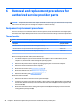


6 Removal and replacement procedures for
authorized service provider parts
CAUTION: Components described in this chapter should be accessed only by an authorized service provider.
Users who access these parts can damage the computer or void the warranty.
Component replacement procedures
There are as many as 74 screws that must be removed, replaced, and/or loosened when servicing the parts
described in this chapter. Make special note of each screw size and location during removal and replacement.
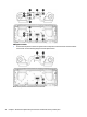
Thermal module
NOTE: The thermal module spare part kit includes replacement thermal material.
Description Spare part number
Thermal module for use only with models with discrete graphics memory 840960-001
Thermal module for use only with models with discrete graphics memory (4 + 4E) 900285-001
Thermal module for use only with models with UMA graphics memory 840961-001
Before removing the thermal module, follow these steps:
1. Turn o the computer. If you are unsure whether the computer is o or in Hibernation, turn the
computer on, and then shut it down through the operating system.
2. Disconnect the power from the computer by unplugging the power cord from the computer.
3. Disconnect all external devices from the computer.
4. Remove the service door (see Service door on page 30).
5. Remove the bottom cover (see Bottom cover on page 31).
6. Disconnect the battery (see Battery on page 32).
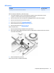
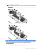
Remove the thermal module:
1. Disconnect the cable for each fan from the system board (1).
2. Loosen the six captive screws (discrete models) or three captive screws (UMA models) in the middle of
the heat sink (between the fans) in the order indicated on the heat sink (2) and the two captive screws
from each fan (3).
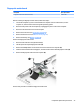
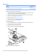
3. Remove the antennas from the routing path atop the left fan (4) and the display connector from the
routing path atop the right fan (4).
40 Chapter 6 Removal and replacement procedures for authorized service provider parts