
HP ZBook Studio G3 Mobile Workstation - Maintenance and Service Guide


Display assembly
NOTE: The DreamColor display assembly is spared as a whole unit assembly only. The LED display assembly
is spared at the subcomponent level only. For more LED display assembly spare part information, see the
individual removal subsections.
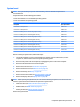
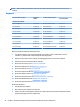
Description Spare part number
15.6-in, UHD, UWVA, DreamColor display assembly not equipped with a webcam 840945-001
15.6-in, UHD, UWVA, DreamColor display assembly equipped with a webcam 840946-001
15.6-in, FHD, UWVA display assembly with a touch screen 840947-001
To remove the display assembly and access the LED display assembly subcomponents, follow these steps:
1. Turn o the computer. If you are unsure whether the computer is o or in Hibernation, turn the
computer on, and then shut it down through the operating system.
2. Disconnect the power from the computer by unplugging the power cord from the computer.
3. Disconnect all external devices from the computer.
4. Remove the service door (see Service door on page 30).
5. Remove the bottom cover (see Bottom cover on page 31).
6. Remove the battery (see Battery on page 32).
7. Remove the thermal module (see Thermal module on page 40).
8. Remove the display cable (see Display cable on page 46).
9. Remove the solid-state drive (see Solid-state drive (M.2) on page 33).
10. Remove the WLAN module (see WLAN module on page 35).
11. Remove the system board (see System board on page 47).
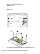
Remove the display assembly:
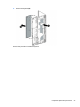
1. Remove the three Phillips PM2.5×4.0 screws (1) that secure each hinge to the computer.
2. Open the computer as far as possible.
54 Chapter 6 Removal and replacement procedures for authorized service provider parts