Best practices for deploying Citrix XenServer on HP StorageWorks P4000 SAN Table of contents Executive summary............................................................................................................................... 3 Business case ...................................................................................................................................... 3 High availability ......................................................................................................
Configuration............................................................................................................................. 33 Implementing Network RAID for SRs ................................................................................................. 33 Configuring Network RAID .......................................................................................................... 34 Pooling XenServer hosts ............................................................................
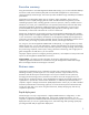
Executive summary Using Citrix XenServer with HP StorageWorks P4000 SAN storage, you can host individual desktops and servers inside virtual machines (VMs) that are hosted and managed from a central location utilizing optimized, shared storage. This solution provides cost-effective high availability and scalable performance. Organizations are demanding better resource utilization, higher availability, along with more flexibility to react to rapidly changing business needs.
“Data de-duplication1” allows you to roll out hundreds of OS images while only occupying the space needed to store the original image. Initial deployment time is reduced to the time required to perform the following activities: Configure “the first operating system” Configure the particular deployment for uniqueness Configure the applications in VMs No longer should a server roll-out take days.
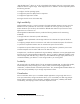
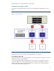
The following section outlines the XenServer storage model. XenServer storage model The XenServer storage model used in conjunction with HP StorageWorks P4000 SANs is shown in Figure 1. Figure 1. XenServer storage model Brief descriptions of the components of this storage model are provided below. HP StorageWorks P4000 SAN A SAN can be defined as an architecture that allows remote storage devices to appear to a server as though these devices are locally-attached.
Performance, capacity and availability can be scaled on-demand and on-line. Storage repository A storage repository (SR) is defined as a container of storage to which XenServer Virtual Machine data will be stored. Although SRs can support locally connected storage types such as IDE, SATA, SCSI and SAS drives, remotely connected iSCSI SAN storage will be discussed in this document.
storage or from storage to storage. Each host acts as an initiator (iSCSI client) connecting to a storage target (HP StorageWorks P4000 SAN volume) in a SR, where the data is stored. Since SCSI commands are encapsulated within an Ethernet packet, storage no longer needs to be locally-connected, inside a server. Thus, storage performance for a XenServer host becomes a function of bandwidth, based on 1 Gb/second or 10 Gb/second Ethernet connectivity.
Clustering and Network RAID Since an individual storage node would represent a single point of failure (SPOF), the HP StorageWorks P4000 SAN supports a cluster of storage nodes working together and managed as a single unit. Just as conventional RAID can protect against a SPOF within a disk, Network RAID can be used to spread a volume’s data blocks across the cluster to protect against single or multiple storage node failures.
Configuring an iSCSI volume The XenServer SR stores VM data on a volume (iSCSI Target) that is a logical entity with specific attributes. The volume consists of storage on one or more storage nodes.
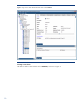
Figure 2. Using CMC to obtain detailed information about volume XPSP2-01 Creating a new volume The CMC is used to create volumes such as XPSP2-01, as shown in Figure 3.
Figure 3. Creating a new volume It is a best practice to create a unique iSCSI volume for each VM in an SR. Thus, HP suggests matching the name of the VM to that of the XenServer SR and of the volume created in the CMC. Using this convention, it is always clear which VM is related to which storage allocation. This example is based on a 10GB Windows XP SP2 VM. The name of the iSCSI volume – XPSP2-01 – is repeated when creating the SR as well as the VM.
Figure 4. Configuring 2-Way Replication and Thin Provisioning You can change volume properties at any time. However, if you change volume size, you may also need to update the XenServer configuration as well as the VM’s OS in order for the new size to be recognized. Comparing full and thin provisioning You have two options for provisioning volumes on the SAN: Full Provisioning With Full Provisioning, you reserve the same amount of space in the storage cluster as that presented to the XenServer host.
When undertaking a project to consolidate servers through virtualization, you typically find underutilized resources on the bare-metal server; however, storage tends to be over-allocated. Now, XenServer’s resource virtualization approach means that storage can also be consolidated in clusters; moreover, thin provisioning can be selected to optimize storage utilization.
have configured a single host in a resource pool, you can scale up with additional hosts to enhance VM availability. The sample SRs configured below utilize the iSCSI volumes described in the previous section.
Figure 5. Turning on NTP using the CMC NTP for XenServer Although NTP Server configuration may be performed during a XenServer installation, the console may also be used post installation. Within XenCenter, highlight the XenServer and select the Console tab. Enable NTP using xsconsole. Enable NTP as shown in Figure 6.
Figure 6. Turning on NTP using the XenServer xsconsole Network configuration and bonding Network traffic to XenServer hosts may consist of the following types: XenServer management VM LAN traffic iSCSI SAN traffic Although a single physical network adapter can accommodate all these traffic types, its bandwidth would have to be shared by each.
Example In the following example, six separate network links are available to a XenServer host. Of these, two are bonded for VM LAN traffic and two for iSCSI SAN traffic. In general, the procedure is as follows: 1. Ensure there are no VMs running on the particular XenServer host. 2. Select the host in XenCenter and open the Network tab, as shown in Figure 7. A best practice for the networks is to add a meaningful description to each network in the description field. Figure 7.
Figure 8. Bonding network adapters NIC 4 and NIC 5 Figure 8 shows the creation of a network bond consisting of NIC 4 and NIC 5 to connect the host to the iSCSI SAN and, thus, the SRs that are common to all hosts. NIC 2 and NIC 3 had already been bonded to form a single logical network link for Ethernet traffic. The network in this example consists of a class C subnet of 255.255.255.0 with a network address of 1.1.1.0. No gateway is configured. IP addressing is set using the pif-reconfigure-ip command. 4.
Figure 9. Renaming network bonds The iSCSI SAN Bond 1 interface is now ready to be used. In order for the bond’s IP address to be recognized, you can reboot the XenServer host; alternatively, use the host-management-reconfigure command. Connecting to an iSCSI volume While HP StorageWorks iSCSI volumes were created in a previous section, no access was assigned to those volumes.
Figure 10. Determining the IQN of a particular XenServer host If desired, you can use the General tab’s Properties button to change the host’s IQN, as shown in Figure 11.
Figure 11. Changing the host’s IQN Note Once you have used the CMC to define an authentication method for an iSCSI volume, if the host’s IQN changes, you must update accordingly. Alternatively, you can update a host’s IQN via CMC’s command-line interface (CLI). Use the hostparam-set command. Note The host’s Universally Unique Identifier (UUID) must be specified. Verify the change using the host-param-list command.
Figure 12. Obtaining the IQN of volume XPSP2-01 Use the following procedure: 1. Under HP-Boulder, highlight the Servers (0) selection. Note that the currently defined authentication rule method is currently zero (0). 2. To obtain the New Server dialog box (as shown in Figure 13), either right-click on Servers (0) and select New ServerSelect Server TasksNew Server or utilize TasksServerNew Server.
Figure 13. New Server dialog box 3. Enter the name XenServer-55b-02. Note that you can choose any name; however, matching the XenServer host name to the authentication method name implies the relationship between the two and makes it easier to assign iSCSI volumes in the CMC. Check Allow access via iSCSI. Check Enable load balancing. Under CHAP not required, enter the IQN of the host (iqn.2009-06.com.example:e834bedd) in the Initiator Node Name field. 4.
Figure 14. Assigning volumes and snapshots to server XenServer-55b-02 Figure 15.
Creating an SR Now that the XenServer host has been configured to access an iSCSI volume target, you can create a XenServer SR. You can configure an SR from HP StorageWorks SAN targets using LVM over iSCSI or LVM over HBA. Note LVM over HBA connectivity is beyond the scope of this white paper. In this example, the IP address of host XenServer-55b-02 is 1.1.1.230; the virtual IP address of the HP StorageWorks iSCSI SAN cluster is 1.1.1.225. Use the following procedure to create a shared-LVM SR: 1.
Figure 17. Naming the SR XPSP2-01 4. As shown in Figure 18, specify the target host for the SR as 1.1.1.225 (the virtual IP address of the HP StorageWorks iSCSI SAN cluster). Next, select Discover IQNs to list visible iSCSI storage targets in a drop-down list. Match the Target IQN value to the IQN of volume XPSP2-01 as shown in the CMC. Select Discover LUNs; then specify LUN 0 as the Target LUN, forcing iSCSI to be presented at LUN 0 for each unique target IQN.
Figure 18. Specify the target IQN and LUN 5. For an LVM over iSCSI SR, raw volumes must be formatted before being presented to the XenServer host for use as VM storage. As shown in Figure 19, any data on a volume that is not in an LVM format will be lost during the format operation. After the format is complete, the SR will be available and enumerated in XenCenter under the XenServer host, as shown in Figure 20.
Figure 19. Warning that the format will destroy data on the volume Figure 20. Verifying that the enumerated SR is shown as available in XenCenter Creating a VM on the new SR Use the following procedure to create a VM on the SR you have just created. 1. From XenCenter’s top menu, select VMNew. 2. Select the desired operating system template for the new VM. In this example, the VM will be running Microsoft® Windows® XP SP2. 3. For consistency, specify the VM’s name as XPSP2-01, as shown in Figure 21.
Note A XenServer host can create an ISO SR library or import a Server Message Block (SMB)/Common Internet File System (CIFS) share. For more information, refer to your XenServer documentation. 5. Specify the number of virtual CPUs required and the initial memory allocation for the VM. These values depend on the intended use of the VM. For example, while the default memory allocation of 512MB is often sufficient, you may need to select a different value based on the particular VM’s usage or application.
The first SR is designated as the default and is depicted by an icon showing a black circle and a white check mark. Note that the default SR is used to store virtual disks, crash dump data, and images of suspended VMs. Figure 23. Verifying that the new VM and SR are shown in XenCenter Summary In the example described above, the following activities were performed: A XenServer host was configured with high-resiliency network bonds for a dedicated SAN and a LAN.
Figure 24. The sample environment Configuring for high availability After virtualizing physical servers that had been dedicated to particular applications and consolidating the resulting VMs on a XenServer host, you must ensure that the host will be able to run these VMs. Designing for high availability means that the components of this environment – from servers to storage to infrastructure – must be able to fail without impacting the delivery of associated applications or services.
Network RAID across the cluster of storage nodes. XenServer host machines also deliver a range of high-availability features, including: Resource pools of XenServer hosts Multiple network interfaces bonded together The use of external, shared storage by VMs VMs configured for high availability To help eliminate SPOFs from the infrastructure, network links configured as bonded pairs can be connected to separate physical switches.
Figure 25. Adding a network switch to remove a SPOF from the infrastructure Note the changes to the physical connections to each switch – in order to be able to survive a switch failure in the infrastructure, each link in each bond must be connected to a separate switch. Configuration Consider the following when configuring your infrastructure: HP StorageWorks P4000 SAN bonds – You must configure the networking bonds for adaptive load balancing (ALB); Dynamic LACP (802.
logical volumes. With Network RAID, which is configurable on a per-volume basis, data blocks are written multiple times to multiple nodes. In the example shown in Figure 26, Network RAID has been configured with Replication Level 2, guaranteeing that a volume remains available despite the failure of multiple nodes. Figure 26.
Figure 27. Configuring Network RAID for a particular volume Pooling XenServer hosts Multiple XenServer hosts can be deployed to support VMs, with each host utilizing its own resources and acting as an individual virtualization platform. To enhance availability, however, consider creating a XenServer host resource pool (that is, a group of similarly-configured XenServer hosts working together as a single entity with shared resources, as shown in Figure 28).
From XenCenter, you can discover multiple XenServer hosts that are similarly configured with resources. Configuring VMs for high availability You can use XenServer’s High Availability (HA) feature to enhance the availability of a XenServer resource pool. When this option is enabled, XenServer continuously monitors the health of all hosts in a resource pool; in the event of a host failure, specified VMs would automatically be moved to a healthy host.
Figure 30. The properties of HP-Boulder-IT-HeartBeat Configuring the resource pool for HA XenServer HA maintains a failover plan that defines the response to the failure of one or more XenServer hosts. To configure HA functionality for a resource pool, select the Pool menu option in XenCenter and click High Availability. The Configure HA wizard now guides you through the setup, allowing you, for example, to specify the heartbeat SR, HP_Boulder-IT-HeartBeat, as shown in Figure 31.
the resource pool changes. For example, if you shut down non-essential VMs or add hosts to the pool, XenServer would make a fresh attempt to restart VMs. You should be aware of the following caveats: XenServer does not automatically stop or migrate running VMs in order to free up resources so that VMs from a failed host can be restarted elsewhere. If you wish to shut down a protected VM to free up resources, you must first disable its HA protection.
Configuring multi-site high availability with a single cluster If your organization deploys multiple data centers in close proximity, communicating over low-latency, high-bandwidth connections4, you can stretch a resource pool between both sites. In this scenario, an entire data center is no longer a SPOF. The stretched resource pool continuously constantly transfers pool status and management information over the network. Status information is also maintained on the 356MB iSCSI shared volume.
Appropriate physical and virtual networks exist at both sites. Alternatively, the multi-site SAN feature can be implemented by correct physical node placement of single site cluster. In a two-site implementation, you need an even number of storage nodes whether you have chosen a single-site cluster or multi-site SAN. Each site must contain an equal number of storage nodes.
Note It is a best practice to physically separate the appropriate nodes or ensure the order is valid before creating volumes. Configuring multi-site high availability with multiple clusters If multiple data centers are located at some distance from each other or the connections between them are high-latency, low–bandwidth, you should not stretch a XenServer resource pool between these sites.
When using an HP StorageWorks P4000 SAN, you would configure a management group at Site A. This management group consists of a cluster of storage nodes and volumes that serve Site A’s XenServer resource pool; all VMs rely on virtual disks stored on SRs; in turn, the SRs are stored on highly-available iSCSI volumes. In order to survive the failure of this site, you must establish a remote snapshot schedule (as shown in Figure 35) to replicate these volumes to the remote site. Figure 35.
Figure 36. Creating a new remote snapshot 4. Set the Recurrence time (in minutes, hours, days, or weeks). Consider the following: – Ensure you leave enough time for the previous snapshot to complete. – Ensure there is adequate storage space at both sites. – Set a retention policy at the primary site based on a timeframe or snapshot count. 5. Select the Management Group for the remote snapshot. 6. Create a remote volume as the destination for the snapshot.
Throttling bandwidth Management groups support bandwidth throttling for data transfers, allowing you to manually configure bandwidth service levels for shared links. In the CMC, right-click the management group, and select Edit Management Group. As shown in Figure 37, you can adjust bandwidth priority from Fractional T1 (256 Kb/sec) to Gigabit Ethernet values. Figure 37.
Figure 38. Changing the direction The CMC may be used with the Volume Failover/Failback Wizard. Refer to the HP StorageWorks P4000 SAN User’s Guide for additional information on documented procedures. Disaster recoverability Approaches to maximizing business continuity should rightly focus on preventing the loss of data and services. However, no matter how well you plan for disaster avoidance, you must also plan for disaster recovery.
Reattaching SRs Backing up configurations You can back up and restore the configurations of the resource pool and host servers. Resource pool configuration You can utilize a XenServer host’s console to back up the configuration of a resource pool. Use the following command: xe pool-dump-database file-name= This file will contain pool metadata and may be used to restore a pool configuration.
Figure 40. Backing up the host configuration The resulting backup file contains the host configuration and may be extremely large. The host may be restored using the following command. xe host-restore host= file-name= Original XenServer installation media may also be used for restoration purposes. Backing up metadata SRs contain the virtual disks used by VMs either to boot their operating systems or store data.
Figure 41. Backing up the VM metadata VM metadata backup data is stored on a special backup disk in this SR. The backup creates a new virtual disk image containing the resource pool database, SR metadata, VM metadata, and template metadata. This VDI is stored on the selected SR and is listed with the name Pool Metadata Backup. You can create a schedule (Daily, Weekly, or Monthly) to perform this backup automatically. The xsconsole command can also be used to restore VM metadata from the selected source SR.
thru changing this data to work with individual snapshots and at best works for only changing the original volume’s UUID and persisting the old UUID with the snapshot. Best practice will suggest limiting the use of the snapshots to the previously suggested use cases. Although no storage limitation is implied with a snapshot as it is functionally equivalent to a read only volume, simplification is suggested over implementing limitless possibilities.
Figure 43. Snapshot rollback It is a best practice to disconnect from the storage repository and reattach to the new rollback storage repository; however, as long as the virtual machine is in a shut down state, the volume may simply be rolled back and virtual machine restarted to the previous state to the rolled back volume.
Figure 45. Reattach storage repositories Once the volume is reattached, a VM needs to be created of the same type and reattached to the virtual disk on that storage repository. Create a new VM, select the appropriate operating system template, provide the appropriate name. The Virtual Disks option may select anything as this will need to be manually changed. Do not select starting the VM automatically as changes still need to occur. Highlight the VM and select the storage tab.
console or from VSS enabled requestors, location of additional application data and logs (within XenServer virtual disks or separate iSCSI volumes), and planning for future growth. An operating system installation size depends upon features chosen during the installation as well as temporary file space. Additional applications installed will also occupy space and are dependent upon what the VM applications are intended to run. Applications may also rely upon data and logging space to be available.
9GB virtual disk is changed to a 20GB virtual disk. Select OK. The virtual disk presented to the VM will now be 20GB. Start the VM. Depending upon the VM’s operating system, different tools must be used to extend a partition and make the extra space known as a file system to the virtual machine. Different options exist, as a new partition may be created or the original partition may be expanded. Third-party tools, such as Partition Magic, also exist and may perform this function.
Process preparing a VM for Cloning Create, install and configure the Windows VM Apply Windows Updates and Service Packs Install Citrix XenTools paravirtualized drivers Install applications and any other desired customization, apply application updates Defragment the hard disk Copy the contents of the \support\tools\deploy.
may leverage space efficiency and will not tie up XenServer host resources. The downside to this process is that although a unique iSCSI volume will be created with duplicated data, the UUIDs of both the storage repository and virtual disk will also be duplicated. Any host seen by XenCenter, including a resource pool, must not share storage repositories or virtual disks with duplicate UUIDs. This management layer depends upon uniqueness.
/dev/sdd is the device path that is required for the next commands and is dependent upon configuration. For example, it may be /dev/sdg or /dev/sdaa. Note the relation of the device bypath to the iSCSI IQN target name for the volume. Step 4 – From the XenServer console in XenCenter. The XPSP2-02-RS-1 storage repository, mapped to device path /dev/sdd, is now used to locate and verify the SR UUID. Note that the appropriate device path value must be used from what was found in Step 3.
Figure 48. Volume group successfully changed Step 7 – From the XenServer console in XenCenter. The XPSP2-02-RS-1storage repository volume group name, VG_XenStorage-13a7f4d6-75c7-8318-6679-eb6702b11de1, will be renamed to represent a new UUID for the storage repository. The “VG_XenStorage-13a7f4d6-75c7-8318-6679eb6702b11de1” will be changed to “VG_XenStorage-13a7f4d6-75c7-8318-6679-eb6702b11de2”. Note that a unique UUID may be chosen by altering a single last alphanumeric.
lvdisplay | grep “VG_XenStorage-da304b0f-fe27-40b2-9034-7799b97b197d” This example will only contain two virtual disks. The command returns two names starting with VHD and concatenated with the virtual disk UUID. Note that in XenServer 5.0, the names started with LV, as shown in Figure 49. Figure 49.New name. Step 9 – From the XenServer console in XenCenter. The XPSP2-02-RS-1 storage repository volume group’s virtual disks need to be renamed.
Figure 50. Each volume group renamed Step 10 – In XenCenter, highlight the XPSP2-02-RS-1 storage repository. Right click on the storage repository and select Detach Storage Repository. Select Yes that the storage repository is to be detached. Right click on the storage repository and select Forge Storage Repository. Select Yes that the storage repository is to be forged. Step 11- In the XenCenter Console, select New Storage. Select the iSCSI Virtual disk storage type.
virtual disk on the XPSP2-02-RS-1 storage repository. Note that the assumption from the New VM Wizard is that a new operating system installation will be required on a new virtual disk. Select the appropriate virtual network interfaces and virtual networks. Do not start the VM automatically as the virtual disk change will need to occur first. Finish the New VM Wizard creation. Highlight the new XPSP2-02-RS-1 VM and select the Storage tab. Detach the virtual disk created by the Wizard.
Figure 53.New SmartClone Volumes Figure 54. Five volumes All 5 of these SmartClone volumes are unique volumes with the original single volume occupying space on the SAN. Each of these volumes may be introduced into the XenServer resource pool as identified in the earlier step. A single golden image of an operating system now serves as the source image for these 5 VMs. Modifications to the UUIDs will persist in its own volume space occupying only what is newly written in its space on the SAN.
initial deployment of SmartClone volumes takes no additional footprint on the SAN, these volumes are fully writeable and may ultimately be completely re-written to occupy an entire volume’s worth of space. Functions such as defragmentation at the file system level may count as additional new writes to the SAN as some operating systems prefer to write new blocks over claiming original blocks. Therefore, it is considered best practice to defragment before a SmartClone is performed.
For more information HP StorageWorks P4000 SANs http://h18000.www1.hp.com/products/storageworks/p4000/ HP StorageWorks P4000 Manuals HP StorageWorks Networks Quick Start Guide http://h20000.www2.hp.com/bizsupport/TechSupport/DocumentIndex.jsp?contentType=Su pportManual&lang=en&cc=us&docIndexId=64179&taskId=101&prodTypeId=12169&prodS eriesId=3936136 Citrix XenServer http://h71019.www7.hp.com/ActiveAnswers/cache/457122-0-0-225-121.html http://www.citrix.com/English/ps2/products/product.