
Specifications


PROMIX20 2 VELLEMAN
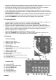
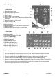
4. Device Layout
a. Top Panel
1. Master output level control
2. Microphone volume control
3. PH1/LN1 - LN2 selector
4. Channel 1 fader
5. Master level stereo VU LED meter
6. CUE (1 channel, cf. #9) or PAN (live output) selector for
headphones
7. Headphones volume control
8. PH3/LN3 - LN4 selector
9. Channel 1 / 2 cue selector
10. Channel 2 fader
11. 6.35mm microphone input on the front panel
12. Channel 1 / 2 crossfader
13. 6.35mm headphones output on the front panel
b. Rear Panel
14. Power Switch
15. Fuse holder for fuse F 0.5A / 250V (5 x 20mm)
16. PHONO3/LINE3 selector
17. PHONO1/LINE1 selector
18. Power cord
19. REC stereo RCA output
20. MAIN stereo RCA output
21. LINE4 stereo RCA input
22. PHONO3/LINE3 stereo RCA input
23. LINE2 stereo RCA input
24. PHONO1/LINE1 stereo RCA input
5. Connections
• Make sure the power switch (#14) is set to “OFF” before making any connections.
• Use only high quality audio cables to minimize sound quality losses.
• Connect your amplifier to the MAIN output (#20) and any recording device to the REC output (#19)
• Connect your microphone to the MIC input (#11) and your headphones to the PHONES output (#13).
• Connect your record players to the PHONO inputs (#22 & 24) and set the selectors (#16 or 17) to PH.
• Connect any line signals to the LINE (LN) inputs (#21 & 23 are line inputs only ; for inputs #22 & 24 you need to
set the switches 16 and 17 to the LN side).
6. Cleaning and Maintenance
1. All screws should be tightened and free of corrosion.
2. The housing, visible parts and the installation location should not be deformed, modified or tampered with.
3. The electric power supply cables must not show any damage. Have a qualified technician maintain the device.
4. Disconnect the device from the mains prior to maintenance activities.
5. Wipe the device regularly with a moist, lint-free cloth. Do not use alcohol or solvents.
6. There are no user-serviceable parts.
7. Contact your dealer for spare parts if necessary.