
Specifications
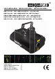

VDP2301RGVLD10 - VDP2601RGYLD10 - VDP3801RGVLD10
11/08/2011 ©Velleman nv
4
• Make sure that the available voltage does not exceed the voltage stated in the specifications of this manual.
• Do not crimp the power cord and protect it against damage. Have an authorised dealer replace it if
necessary.
• Disconnect the device from the mains to clean it or when it is not in use. Handle the power cord by the plug
only.
• Keep the device away from splashing and dripping liquids. Never put objects filled with liquid on top of the
device.
• Note that damage caused by user modifications to the device is not covered by the warranty.
• Mechanical wear is not covered by warranty.
• Keep the device away from children and unauthorised users.
3. General Guidelines
Refer to the Velleman® Service and Quality Warranty on the last pages of this manual.
• Nor Velleman nv nor its dealers can be held responsible for any damage (extraordinary, incidental or
indirect) – of any nature (financial, physical…) arising from the possession, use or failure of this product.
• This device is designed for professional use on stage, in discos, theatres, etc. The laser projector should
only be used indoors with an alternating current of max. 230VAC / 50Hz.
• Lighting effects are not designed for permanent operation: regular operation breaks will prolong their lives.
• Do not shake the device. Avoid brute force when installing or operating the device.
• Select a location where the device is protected against extreme heat, dust and moisture.
• Use an appropriate safety cable to fix the device (e.g. VDLSC7 or VDLSC8).
• Familiarise yourself with the functions of the device before actually using it. Do not allow operation by
unqualified people. Any damage that may occur will most probably be due to unprofessional use of the
device.
• Use the original packaging if the device is to be transported.
• All modifications of the device are forbidden for safety reasons.
• Only use the device for its intended purpose. All other uses may lead to short circuits, burns, electroshocks,
crash, etc. Using the device in an unauthorised way will void the warranty.
4. Mounting/connecting the device
• Have the device installed by a qualified person, respecting EN 60598-2-17 and all other applicable norms.
• The carrying construction must be able to support 10 times the weight of the device for 1 hour without
deforming.
• The installation must always be secured with a secondary attachment e.g. a safety cable.
• Never stand directly below the device when it is being mounted, removed or serviced. Have a qualified
technician check the device once a year and once before you bring it into service.
• Install the device in a location with few passers-by that is inaccessible to unauthorised persons.
• Overhead mounting requires extensive experience: calculating workload limits, determining the installation
material to be used… Have the material and the device itself checked regularly. Do not attempt to install the
device yourself if you lack these qualifications as improper installation may result in injuries.
• Adjust the desired inclination angle via the mounting bracket and tighten the bracket screws.
• Make sure there is no flammable material within a 0.5m radius of the device.
• Have a qualified electrician carry out the electric connection.
• Connect the device to the mains with the power plug. Do not connect it to a dimming pack.
• The installation has to be approved by an expert before the device is taken into service.
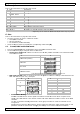
• For installations using DMX512:
• Connection
Connect the provided XLR cable to the female 3-pin XLR output of your controller and the other side to
the male 3-pin XLR input of the laser projector [7]. Multiple laser projectors can be linked through serial
linking. The linking cable should be a two-core screened cable with XLR input and output connectors (see
page 2 for pin-out).
• Chain with Termination
A DMX terminator is recommended for installations where the DMX cable has to run a long distance or is
in an electrically noisy environment (e.g. discos). The terminator prevents corruption of the digital control
signal by electrical noise. The DMX terminator is simply an XLR plug with a 120Ω resistor between pins 2
and 3, which is then plugged into the XLR output socket [8] of the last device in the chain (see page 2).
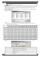
• For installations using ILDA (PC mode) use following ILDA cable layout (DB-25F):
PIN signal name remarks
1 X+ -5V to +5V
2 Y+ -5V to +5V
5 Red+ 0V to 2.5V
6 Green+ 0V to 2.5V
14 X- Connected to ground
15 Y- Connected to ground
18 Red- Connected to ground
19 Green- Connected to ground
25 Ground Cable shield