
User manual


VDP750ST
24.09.2010 ©Velleman nv
4
means of the red DIP switch on the device. Switch it in the ON position if the device is the last device in
the chain.
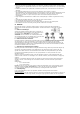
c. Projector DMX start address selection
All DMX-controlled devices need a digital start address so that the correct device responds to the signals.
This digital start address is the channel number from which the device starts to “listen” to the DMX
controller. Set the correct number by means of the DIP switches on the device.
You can use the same starting address for a whole group of devices or enter an individual one for every
device.
When all devices have the same address, all the units will “listen” to the control signal on one particular
channel. In other words: changing the settings of one channel will affect all devices simultaneously. If
you set different addresses, each device will “listen” to a separate channel number. Changing the settings
of one channel will only affect the device in question.
DMX channels:
• Ch 1: strobe rate
• Ch 2: strobe dimmer
! Warning: Ch2 to 0% and Ch1 from 10 to 85% creates a blinder effect. The level of CH1 is the dimming
level of the blinder effect. This may only last for max. 5 seconds, otherwise the lamp may get
damaged. When CH1 is higher than 85%, the strobe turns into stand-alone mode with music-controlled
function on.
d. Function selection
There are 10 DIP switches ; the way these are set determines the operation mode of the device.
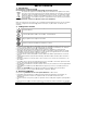
DMX address setting
Set DIP switch 10 to ON (up). Now use the first 9 switches to determine the address. The 9 switches
each have a different value, which is always one more than the sum of all switches before it. This means
switch 1 has value 1, switch 2 has value 2, switch 3 has value 4, 4 is 8, 5 is 15, 6 is 32, 7 is 64, 8 is 128
and 9 is 256. Take the address you want to give to the device and start counting from switch 9 to 1,
selecting the values that need to be added along the way. Set the corresponding switches to ON. The
maximum value is 511 (all 9 switches are ON).
Test program
Switch 10 must be OFF (down).
This function allows you to perform the automatic test program (switch 9 OFF) or to set the speed and
dimmer functions yourself (switch 9 ON).
For the automatic test program, the value of the first 8 switches does not matter, as long as they are not
all ON.
In the manual program, switches 1-4 are used to set the speed and switches 5-8 are used to set the
dimmer function.
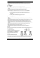
The table below indicates you the switches should be set to determine speed and dimmer function (16
levels each):
level DIP switch setting level DIP switch setting
0 (slow) OFF – OFF – OFF – OFF 8 OFF – OFF – OFF – ON
1 ON – OFF – OFF – OFF 9 ON – OFF – OFF – ON
2 OFF – ON – OFF – OFF 10 OFF – ON – OFF – ON
3 ON – ON – OFF – OFF 11 ON – ON – OFF – ON
4 OFF – OFF – ON – OFF 12 OFF – OFF – ON – ON
5 ON – OFF – ON – OFF 13 ON – OFF – ON – ON
6 OFF – ON – ON – OFF 14 OFF – ON – ON – ON
7 ON – ON – ON – OFF 15 (fast) ON – ON – ON – ON
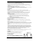
Music control
This function sets the device to music-controlled. Switches 1-8 must be ON, switches 9 and 10 must be
OFF.
6. Maintenance
1. All screws should be tightened and free of corrosion.
2. The housing, the lenses, the mounting supports and the installation location (e.g. ceiling, suspension,
trussing) should not be deformed, modified or tampered with e.g. do not drill extra holes in mounting
supports, do not change the location of the connections …
3. Mechanically moving parts must not show any signs of wear and tear.