
User manual
PROMIX230DSP HQPOWER
6
Tracks that do not contain clear and constant beats will not be accurately tracked by the ABS and will therefore produce
erratic readings.
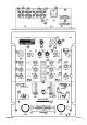
20. BPM Display Channel 1
21. BPM Display Channel 2
22. BPM Offset Indicator
This is an additional feature to the BPM display that allows you to visually track the difference in BPM between the two
music sources. The 7-LED display will illuminate a single LED at a time and favour towards the channel with the faster
BPM, e.g. if channel 1 is faster the lit LED will be towards the left and towards the right for channel 2. When the BPMs
are matched the blue LED in the centre of the display will illuminate. For this feature to function, the difference between
the two sources must be 10 BPM or less. If the difference is greater, the LEDs will not light.
23. Microphone Input
An XLR and ¼” jack combination is mounted on the front face of the mixer offering a balanced or unbalanced connection.
24. Microphone Gain
This control changes the level of the microphone. It will accommodate most microphones of both low and high
impedances up to 600Ω (range < -30dB ~ + 52dB).
25. Microphone EQ Control HI
Cut and boost control over high frequencies of the microphone input.
26. Microphone EQ Control LO
Cut and boost control over low frequencies of the microphone input. Excessive bass can lead to amplifier overload on the
mixer output. If distortion is heard, reduce the gain control to compensate.
27. Microphone Function Switch
This switch offers the facility to attenuate the main music program automatically when the microphone input is active.
OFF: this switches the microphone signal off.
ON: this places the microphone on air.
O’RIDE: when selected, the live music program will be attenuated by 12dB when the microphone is used.
28. Cue/Output Display
A 10-segment LED ladder with PPM characteristics and peak hold facility on - 9dB ~ + 8dB relative. Indication range is
- 22 ~ + 8dB.
Digital Signal Processor
29. LCD
2 lines and 16 characters LCD interface which indicates all 99 preset names plus an audio input level meter. The upper
display line is acting as an analogue bargraph level meter. The indicated audio level is independent of the selected preset.
If the effects switch is switch off, the bargraph level meter indication will be replaced by [EFFECT MUTED]. The lower
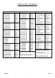
display line indicates the selected preset with number and the associated name (see table on page 3).
30. Assign
This selector lets you determine which input signals are routed to the DSP processor.
31. Effect On Switch
Use this switch to run the effect on or off.
32. Up/Down
These keys allow you to select the different programs. A continuous pressed key will increase the preset number at
scrolling speed.
33. Return Level Control
This control is used to determine the volume of the effects signal.
34. Phono Inputs
Stereo phono inputs (input impedance = 47k Ω, source impedance = typical magnetic cartridge, input sensitivity = 5.5mV
RMS (- 42dBu) max.).
35. CD Inputs
Input impedance = typically 10k Ω, source impedance = 2k Ω max., nominal sensitivity = 775mV RMS (0dBu).
36. Line Inputs
Input impedance = typically 10k Ω, source impedance = 2k Ω max., nominal sensitivity = 775mV RMS (0dBu).
37. Unbalanced Master Output (High)
Stereo output program is provided by standard unbalanced phono sockets. Level = + 6dBu (1.55V RMS), output
impedance = < 50Ω, load impedance = 5k Ω max.