
Operation Manual
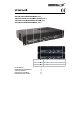


VPASGx00
11.05.2010 ©Velleman nv
4
• Switch on the amplifier last and switch it off first. Disconnect from the mains when not in use or when
maintenance activities are performed. Handle the power cable by the plug only.
• Keep power cables away from signal cables to avoid interference.
• Save this user manual for further reference.
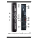
4. Overview and use
Refer to the illustration on page 2 of this manual.
1 Clip LED This LED flashes when the channel A output signal is distorted.
2 Gain control: channel A Adjust the volume of channel A.
3 Power LED This LED illuminates when the amplifier is switched on.
4 Protect LED On when one of the internal protection circuits is active or no speakers are
connected. Switch off the amplifier and resolve the error condition .
5 Gain Control: channel B Adjust the volume of channel B.
6 Clip LED This LED flashes when the channel A output signal is distorted.
7 Power switch Press this button to start operation.
8 Speakon
®
output Speakon
®
speaker jack sockets.
9 TRS input sockets for input signals using balanced ¼”
T
RS (stereo) jacks
10 RCA input sockets for input signals using unbalanced phone (RCA) input jacks
11 Ground lift switch Some connected equipment may present hum. This switch will remove the
signal ground and reduce the effect of the mains hum.
12 TRS output sockets for output signals using stereo jacks
13 screw outputs for output signals using bare wires
14 fuse holde
r
Only replace the fuse when the device is disconnected from the
Mains. Only use fuses of the same rating and power.
15 AC power socket plug the AC power cord into this power socket
16 AC voltage selecto
r
Make sure the setting matches your local mains voltage!
5. Notes
• Rack installation
This amplifier can be mounted in a 19” (483mm) rack that allows access to front and rear panel. Make
sure to leave enough space around the device for sufficient ventilation. Note that when mounting in a
rack, the heaviest devices should be mounted closest to the bottom.
Also note that it is not enough to mount the amplifier with 4 screws on the front; the rear must also be
attached to the side bars of the rack.
• Input cables
Using short cables will improve sound quality as high frequencies are absorbed by the cable. Longer
cables may also lead to humming and noise problems. If you do need longer cables, only use balanced
cables.
• Output cables
The high damping factor of the amplifier produces a clear sound reproduction. Long and thin cables will
influence this damping factor and thus the low frequencies in a negative way. To maintain good sound
quality, the damping factor should be around 50. When long cables are unavoidable, make sure they
are thick enough.
• Speakers
Connect your speakers using the Speakon
®
or screw outputs. Connect the red terminator with the
positive wire and the black terminator with the negative wire.
• Ground lift switch
This switch allows the signal ground or chassis ground to be separated in case of a ground conflict. For
safety reasons it is recommended to keep the switch in the GND FLOATING position unless ground
problems are experienced.