
Specifications


Mains Connection
The supply transformer has been designed for use either 115V AC or 230V AC,
selected by slide switch on rear panel. The amplifier is factory set at 230V AC mains
voltage.
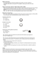
Battery Connection (12V DC for 20W / 40W, 24V DC for 60W)
When using external batteries, earth the amplifier via the screw terminal because there are high
voltages present. Electrical stability of the system will be increased by earthing the case.
NOTE: The connection cable must be fitted with an in-line fuse, quick blow type (20W : 6.3A,
40W :10A , 60W : 8A). When connecting batteries please ensure correct polarity.
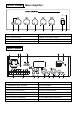
Microphone Connections
Mic1 input is either a balanced standard 6.35mm stereo jack on the front panel or XLR and DIN
on the rear panel (With selectable phantom power). Wiring is as follows:
XLR (Balanced Operation)
Pin1 : Screen
Pin2 : Signal (live)
Pin3 : Signal (return)
DIN (Balanced operation)
Pin1 : Signal (live)
Pin2 : GND
Pin3 : Signal (return)
Pin4 : Priority Control
Pin5 : GND
6.35mm Stereo Jack Plug (Balanced operation)
Tip : Signal (live)
Ring : Signal (return)
Sleeve : Screen
Mic1 input has VOX priority which will override both Mic2 and Aux input signals but
NOT the TEL/EMER input.
Mic1-2 input are XLR, DIN and phone jack with selectable phantom power located on the
rear panel and wired as above. The phantom power is factory set and can be enabled as
follows:
1. Remove the power lead from the AC wall socket.
2. Remove the top cover.
3. Locate the link pins (Marked SW102) on the Printed Circuit Board behind the microphone
XLR input socket.
4. Connect the black shorting plug to the centre pin and ON position to enable the phantom
power.
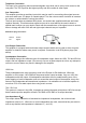
Chime
Switch on the chime on/off switch on the rear panel and short the pin4, pin5 of DIN
socket or short the sleeve and ring of phone plug Mic 1. This will activate the chime function
(“Ding-Dong” attention signal preceding a call). The default volume of the chime is pre-set at the
factory and is adequate for most applications.
1
4
2
5
3
21
3