
User manual

ARTIKELNUMMER
12.321.xx.310
Auswahl des Gerätetyps
14 ZDP Drehstrommessrelais ohne N
15 ZDP Drehstrommessrelais mit N
ZDP
L1
L2
L3
H S B
ZDP
L1
L2
L3
H S B
ZDP
L1
L2
L3
H S B
ZDP
H S B
L1
L2
L3
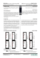
Rechtsdrehfeld
alle LED´s leuchten
Relais ist angezogen
Linkssdrehfeld
alle LED´s blinken in
falscher Reihenfolge
Phasenausfall
entsprechende LED
erlischt
Unterspannung /
Asymmetriefehler
entsprechende LED blinkt
|H|S|B| Industrieelektronik GmbH
Hans-Bördlein-Str. 10
97723 Oberthulba/Germany
Tel.: +49 9736 / 75759 - 0
Fax: +49 9736 / 75759 - 20
info@hsb-electronics.de
www.hsb-electronics.de
Industrieelektronik GmbH
| | | |
H S B
Messrelais
Drehstrommessrelais / Phasenfolge ZDP
Baureihe 17,5mm mit 1 Wechsler
measuring relay
ZDP phase measuring relay / phase sequence
type 17,5mm with 1 changeover
ANWENDUNG
Zur Vermeidung falscher Drehrichtungen an Motoren
und Ausfallerkennung einzelner Phasen im
Drehstromnetz.
BESCHREIBUNG
Das Gerät überwacht die drei Phasen eines
Drehstromnetzes auf Phasenfolge und Phasenausfall.
Das Gerät ohne Neutralleiterüberwachung bezieht seine
Versorgungsspannung aus allen drei Phasen, während
das Gerät mit Neutralleiterüberwachung seine
Versorgungsspannung aus L1 und N bezieht .
Das Anliegen der einzelnen Phasen wird durch separate
LED´s angezeigt.
FUNKTION
Das Messrelais schaltet in seine Arbeitsstellung sobald alle
drei Phasen 170V AC (Phasen - N) bzw. 295V überschreiten
und die Phasenfolge rechtsdrehend ist. Dieser Zustand wird
durch das Leuchten der drei LED´s angezeigt.
Unterschreitet mindestens eine der drei Phasen die
Mindestspannung oder liegt ein Linksdrehfeld vor, so fällt
des Relais in seine Ruhelage zurück. Bei Überwachen
eines Linksdrehfeldes werden zwei Phasen am
Drehstrommessrelais ZDP miteinander getauscht.
Zur Überwachung von Wechselstromnetzen mit 230V
Versorgungsspannung müssen die Phasenanschlüsse L1
und L2 gebrückt werden und L3 darf nicht angeschlossen
werden. Ebenso ist hierzu ein Neutralleiteranschluss
notwendig.
BETRIEBSZUSTANDSANZEIGEN
PART NUMBER
12.321.xx.310
Selection of device type
14 ZDP without neutral conductor (N)
15 ZDP with neutral conductor (N)
ZDP
L1
L2
L3
H S B
ZDP
L1
L2
L3
H S B
ZDP
L1
L2
L3
H S B
ZDP
H S B
L1
L2
L3
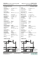
Clock wise rotation
all LED´s on
Relay is on
left rotation
all LED´s are flashing
in wrong way
phase loss
individual LED is of
f
under voltage / asymetry
failure
individual LED is flashing
APPLICATION
Correct rotation of three-phase motors.
DESCRIPTION
The ZDP phase measuring relay / phase
sequence measures the phases of a three-phase
system (400V AC) for phase sequence and phase
failure. The relay is powered by the connection to
phase L1, L2 and L3.
FUNCTION
The measuring relay switches into its work position as soon
as all three phases exceed 170V AC (phases – N) and the
phase sequence turns clockwise. This status is indicated by
all three red leds. The relay switches into its rest position if at
least one of the phases falls below the minimum value of
170V AC (phases – N) or a counter clockwise rotation occurs.
To monitor a possible counter clockwise rotation, simply
switch the connections of two of the three phases.
INDICATORS