6 V2 V2.0 the productivity, Pl Bb ws, and other matters of attention Please tog Ins www hsdre.
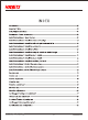
INDEX introduction 3 important hints 03 SAY FAT INS RUCTIONS =m mm mmm 04 Description of each COMPONENT ones nnn 08 Install instructions 1:0pen the Box eee 09 install instructions 2: Install the nose and fuselage nen 10 Install instructions 3: Install the left and right horizontal fails 10 install instructions 4: install the vertical fail ces mmm] 10 install instructions 5: install the tail ding ee] 10 install instructions 6: install the wing-tip missile or missile hanger mec il install instructions 7: inst
introduction Thank you so much for purchasing HF-16 Jet plane, What you have now is the latest HF-18 Jet plane product of HEADSETS. This model has the following features: 01.The wing is designed and produced by using the new mold, and the wing area is increased by 20%. 02.4 set of auxiliary fuel tanks and two sets of missiles have been added under the wing to make it more realistic, 03. Wing tip missile upgrade to 2 models, 04.
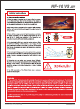
HEADSETS' Safety Flight Instructions Strongly suggestion: users while enjoying the flying, please ensure that you are in a safe and reasonable environment. 1. It Is better to try to choose an empty airspace and no obstacles conditions when you fly. 2. Stay away from people, animals, buildings, trees, water and other obstacles during flying, 3. Please keep the radio transmitter in your hand during the flight to control the model at any time to prevent accidents, 4.
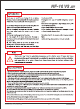
Warm Prompt The use life of the turbine is directly related to the operation environment and operation methods. The turbine uses the most streamlined structure to achieve the most extreme working state. Each spare parts designed and produced in the extreme, and the working conditions are extremely harsh, Da not dismantle the inlet and spindle structures by yourself. In case the turbine is dismantled, it must be re-installed in accordance with the specifications to achieve the original performance.
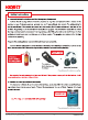
HEADSETS' Safety Instructions 2. Personal Safety Protection and Fire Emergency Equipment Carbon dioxide extinguishers should be prepared at any time and placed within 2 meters of the engine, In case of danger, persons present can use it immediately. Dry powder fire extinguisher is strictly prohibited. if the powder Is sprayed into the turbine, it will cause serious wear and tear of the turbine. Suggesting to use of soundproof earmuffs and goggles.
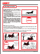
Safety Instructions 4, Other security matters * When the engine is running, the air intake is like the vacuum, Do not draw your hand close to the air intake of the engine to prevent it from being inhaled. The air intake should be kept clear and the signal transmission wire should be properly fixed, # The engine inlet is suggested to be equipped with protective isolation net to prevent serious damage to the engine caused by foreign bodies.
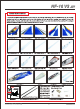
Description of each component HEADSETS' Nose antenna Nose Cockpit Right 1# missiles Right 2# missiles Nose landing gear Right wingtip missiles Front landing gear Right main wing Right aileron Vertical tail Rudder hatch door Left aux Fuselage Right horizontal tail {Right elevator } Fuselage antenna Left horizontal tail {Left elevator) Retailer Left 1# missiles Left wingtip missiles Left main wing Heartrending gear tanker Left 2# mis: www.hsdre.
Install instructions 1.
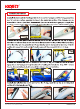
HEADSETS' Install instructions 2.Install the Nose and the Flagellate the Nose and the Fuselage out of the PE bag, place them on a flat and clean surface, assemble the Nose to the designated position of the fuselage, and use screws (HA3 X 14mm X PCs) fixed. Recommend: If you want to be firmer, Suggest you can apply EPO uninstall the left and right Horizontal tail: Take out the left and right flat tails from the PE bag and place them on a flat and clean surface.
Install instructions 6.Install the wing-tip missile or missile hanger: Take out the wing, wing-tip missile or missile hanger from the PE bag. The wing-tip missile and missile hanger can only be chosen ona in option. Select the wingtip missile that needs to be assembled and assemble it to the designated slot of the wing and pull it back. Pulling the assembly back in place will make a popping sound, justifying that the assembly's in place. i | 7.Install the No. 1 missile:Remove the No.
HEADSETS' Install instructions 10. Instzil the main passing the main wing pin rod (10mm X L400mm X PCs} through the designated hole of the fuselage, assemble it into the main wing pin rod fixing seat hole, and lock the screw. Then align the holes of the left and right main wings with the main wing pin rods, and insert the pin rods. Make sure that the signal cables of the main wing end and the fuselage end are connected before they are fully inserted, and then fix them with screws (HM3 X 10mm X 4pcs). 1i.
First test and adjustment after assembly 1. To find the 5-BUS line at the location 2. Connect the Super integrated 3. Open the radio transmitter. of the Super Integrated Control Box and connected to the receiver S-BUS port. control box with 2 sets of 25 lip Note: If the receiver does not support $batteries; BUS, the integrated control box needs to be connected to the PWM signal line connection; ] 5. Check the Super Integrated Control Box S-BUS meed channel settings.
HEADSETS' First test and adjustment after assembly Aileron adjustments After the selling, the standard petition of the rudder surface will be adjusted. The aileron rudder surface should be in the same plane as the wing. (there is an upward or downward adjustment, it can be adjusted by physical adjustment or system adjustment; {1}. Physical adjustment: by (2).
First test and adjustment after assembly Elevation adjustment; After the setting, the standard position of the rudder surface will be adjusted, The rear edge of elevator should be flush with the upper edge of the fuselage as the benchmark. if there is an upward or downward adjustment, it can be adjusted by physical adjustment or system adjustment; {1}. Change the angle of the rudder surface by {2}.
HEADSETS' First test and adjustment after assembly Possible direction reverse action When the direction action is opposite to the specified action, you can adjust it with the 2 ways as below: {1}. to find the reverse setting menu of direction in the radio transmitter menu, and switch in the direction item to the forward direction. {2).
First test and adjustment after assembly 9. Landing gear testing and adjustment: Check whether the landing gear is working properly.
HEADSETS' First test and adjustment after assembly 19. Ground test and adjustment: After the above process Is gradually completed, power the plane and do straight slide test to check whether the stroke volume of the front steering servo is full. If the steering is yaw or the steering angle Is too large, It can be adjusted by physical adjustment or system adjustment: yaw adjustment: @, physical adjustment: Complete it by adjusting the length of the front wheel steering rod; @.
First test and adjustment after assembly 11. Pr-takeoff center of gravity test: Before the aircraft takes off, it is necessary to confirm whether the center of gravity of the aircraft is correct. The center of gravity is located behind the front edge of the main wing: 155~160mm. Battery assembly diagram C6: 1551 ome & General method for testing tha center of gravity. Canter of gravity adjustment: If the center of gravity position is not correct, it must be adjusted.
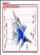
HEADSETS’ Specification and configuration Specifications: Wingspan 134d mm /528in Length 1808 mm /71.2In Take off weight 8.5 kg / 18.7 Ib {with 1800cc Aviation kerosene) Cruising speed 150-200 km/h Flying time 3~5 minutes Main wing area 47.6dm’ Loading of airfoil surface 178.