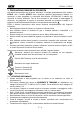
© Copyright HT ITALIA 2012 Release 1.
Indice generale General index Índice general Inhalt ITALIANO ......................... IT - 1 ENGLISH ......................... EN - 1 ESPAÑOL ........................ ES - 1 DEUTSCH ........................
ITALIANO Manuale d’uso © Copyright HT ITALIA 2012 Versione IT 1.
HT9014 - HT9015 Indice: 1. PRECAUZIONI E MISURE DI SICUREZZA ................................................................. 2 1.1. 1.2. 1.3. 1.4. 2. DESCRIZIONE GENERALE ......................................................................................... 4 2.1. 2.2. 3. Strumenti di misura a Valore medio e in Vero Valore Efficace.......................................... 4 Definizione di Vero Valore Efficace e fattore di cresta ......................................................
HT9014 - HT9015 1. PRECAUZIONI E MISURE DI SICUREZZA Nel seguito del manuale con la parola “strumento” si intende genericamente sia il modello HT9014 che il modello HT9015 salvo notazione specifica all’occorrenza indicata. Lo strumento è stato progettato in conformità alla direttiva IEC/EN61010-1 relativa agli strumenti di misura elettronici.
HT9014 - HT9015 1.2.
HT9014 - HT9015 2.
HT9014 - HT9015 3. PREPARAZIONE ALL’UTILIZZO 3.1. CONTROLLI INIZIALI Lo strumento, prima di essere spedito, è stato controllato dal punto di vista elettrico e meccanico. Sono state prese tutte le precauzioni possibili affinché lo strumento potesse essere consegnato senza danni. Tuttavia si consiglia, comunque, di controllare sommariamente lo strumento per accertare eventuali danni subiti durante il trasporto. Se si dovessero riscontrare anomalie contattare immediatamente lo spedizioniere.
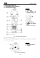
HT9014 - HT9015 4. ISTRUZIONI OPERATIVE 4.1. DESCRIZIONE DELLO STRUMENTO 4.1.1. Descrizione dei comandi LEGENDA: 1. Toroide apribile 2. LED luminoso per indicazione tensione AC senza contatto 3. Leva apertura toroide 4. Selettore funzioni 5. Tasto HOLD / 6. Tasto PK/REL 7. Display LCD 8. Tasto MODE 9. Tasto Hz% 10. Tasto MAX/MIN 11. Terminale di ingresso VΩ CAPHz%Temp 12. Terminale di ingresso COM 13. Coperchio vano batteria Fig. 1: Descrizione dello strumento 4.1.2.
HT9014 - HT9015 4.2. DESCRIZIONE DEI TASTI FUNZIONE 4.2.1. Tasto H Una pressione del tasto “H” attiva la funzione di Data HOLD, ovvero il congelamento del valore della grandezza misurata. Sul display appare il messaggio "HOLD". Questa modalità di funzionamento viene disabilitata qualora si prema nuovamente il tasto “H” o si agisca sul commutatore. 4.2.2.
HT9014 - HT9015 4.3. DESCRIZIONE DELLE FUNZIONI DEL COMMUTATORE 4.3.1. Misura di Tensione AC ATTENZIONE La massima tensione AC in ingresso è 1000Vrms. Non misurare tensioni che eccedano i limiti espressi in questo manuale. Il superamento di tali limiti potrebbe causare shock elettrici all’utilizzatore e danni allo strumento. 1. 2. 3. 4. 5. 6. Fig.
HT9014 - HT9015 4.3.2. Misura di Tensione DC ATTENZIONE La massima tensione DC in ingresso è 1000V. Non misurare tensioni che eccedano i limiti espressi in questo manuale. Il superamento di tali limiti potrebbe causare shock elettrici all’utilizzatore e danni allo strumento. Fig. 4: Uso della pinza in misura di Tensione DC 1. Selezionare la posizione 2. Inserire il cavo rosso nel terminale di ingresso VΩ CAPHz%Temp e il cavo nero nel terminale di ingresso COM (Fig. 4) 3.
HT9014 - HT9015 4.3.3. Misura di Resistenza ATTENZIONE Prima di effettuare una qualunque misura di resistenza accertarsi che il circuito in esame non sia alimentato e che eventuali condensatori presenti siano scarichi. Fig. 5: Uso della pinza per misura di Resistenza 1. Selezionare la posizione Ω CAP 2. Inserire il cavo rosso nel terminale di ingresso VΩ CAPHz%Temp e il cavo nero nel terminale di ingresso COM 3. Posizionare i puntali nei punti desiderati del circuito in esame (Fig. 5).
HT9014 - HT9015 4.3.4. Test Continuità e Prova Diodi ATTENZIONE Prima di effettuare una qualunque misura di resistenza accertarsi che il circuito in esame non sia alimentato e che eventuali condensatori presenti siano scarichi. Fig. 6: Uso della pinza per Test Continuità e Prova Diodi 1. Selezionare la posizione Ω CAP 2. Premere il tasto MODE ciclicamente fino a visualizzare il simbolo “ ” a display per attivare il test continuità 3.
HT9014 - HT9015 4.3.5. Misura di Capacità ATTENZIONE Prima di eseguire misure di capacità su circuiti o condensatori, rimuovere l’alimentazione al circuito sotto esame e lasciare scaricare tutte le capacità presenti in esso Fig. 7: Uso della pinza per misura di Capacità 1. Selezionare la posizione Ω CAP 2. Premere il tasto MODE ciclicamente fino a visualizzare il simbolo “nF” a display 3. Inserire il cavo rosso nel terminale di ingresso VΩ CAP Temp e il cavo nero nel terminale di ingresso COM 4.
HT9014 - HT9015 4.3.6. Misura di Temperatura ATTENZIONE Non porre la sonda di temperatura a contatto con superfici sotto tensione. Tensioni superiori a 30Vrms o 60VDC comportano rischi di shock elettrico Fig. 8: Uso della pinza per misura di Temperatura 1. Selezionare la posizione Temp 2. Premere il tasto MODE per selezionare il tipo di misura. I simboli “°C” o “°F” sono visualizzati a display in funzione della misura in gradi Centigradi o Farheneit 3.
HT9014 - HT9015 4.3.7. Misura di Corrente DC (solo HT9015) ATTENZIONE Assicurarsi che tutti i terminali di ingresso dello strumento siano disconnessi Fig. 9: Uso della pinza per misure di corrente DC 1. Selezionare le posizioni 60A o 600A del selettore 2. Premere il tasto MODE per selezionare il tipo di misura “DC” 3. Premere il tasto PK/REL per azzerare la corrente di magnetizzazione residua ATTENZIONE L’azzeramento della corrente di magnetizzazione residua è essenziale per ottenere risultati corretti.
HT9014 - HT9015 4.3.8. Misura di Corrente AC ATTENZIONE Assicurarsi che tutti i terminali di ingresso dello strumento siano disconnessi Fig. 9: Uso della pinza per misure di corrente AC 1. Avvicinare lo strumento in prossimità di una sorgente AC e notare l’accensione del LED rosso alla base del toroide (vedere Fig. 1 – parte 2) che sottolinea la presenza di tensione 2. Selezionare le posizioni 60A∼ o 600A∼ (solo HT9014) oppure 60A o 600A (solo HT9015) del selettore 3.
HT9014 - HT9015 4.3.9. Misura di Frequenza e Duty Cycle ATTENZIONE • Nella misura di frequenza con puntali la massima tensione AC in ingresso è 1000Vrms. Non misurare tensioni che eccedano i limiti espressi in questo manuale. Il superamento di tali limiti potrebbe causare shock elettrici all’utilizzatore e danni allo strumento • Nella misura di frequenza con toroide assicurarsi che tutti i terminali di ingresso dello strumento siano disconnessi Fig.
HT9014 - HT9015 5. MANUTENZIONE 5.1. GENERALITÀ 1. Lo strumento da Lei acquistato è uno strumento di precisione. Durante l’utilizzo e l’immagazzinamento rispettare le raccomandazioni elencate in questo manuale per evitare possibili danni o pericoli durante l’utilizzo. 2. Non utilizzare lo strumento in ambienti caratterizzati da elevato tasso di umidità o temperatura elevata. Non esporre direttamente alla luce del sole. 3. Spegnere sempre lo strumento dopo l’utilizzo.
HT9014 - HT9015 6. SPECIFICHE TECNICHE 6.1. CARATTERISTICHE TECNICHE L’incertezza è calcolata come ± [% lettura + (numero di cifre) x risoluzione]. Essa è riferita alla temperatura 18°C ÷ 28°C con umidità relativa <75% RH Tensione DC (Autorange) Campo Risoluzione Incertezza Impedenza di ingresso Protezione contro i sovraccarichi 600.0mV 6.000V 60.00V 600.0V 1000V 0.01mV 0.001V 0.01V 0.1V 1V ±(1.
HT9014 - HT9015 Corrente AC TRMS (strumento HT9014) Campo Risoluzione Incertezza (*) 60.00A 600.0A 60.00A 600.0A 0.01A 0.1A 0.01A 0.1A ±(2.8%lett.+12cifre) ±(2.8%lettura+8cifre) ±(4.5%lett.+10cifre) ±(5.0%lett.+10cifre) Banda passante Protezione contro i sovraccarichi 50 ÷ 60Hz 600AACrms 61 ÷ 400Hz Funzione PEAK: tempo di risposta <10ms ; (*) Riferita a cavo posizionato al centro del toroide Influenza del posizionamento del cavo: ±2.
HT9014 - HT9015 6.1.1. Norme di Sicurezza Lo strumento è conforme alle norme: IEC/EN61010-1 Isolamento: doppio isolamento Livello di Inquinamento: 2 Max altitudine di utilizzo: 2000m Categoria di sovratensione: CAT IV 600V, CAT III 1000V verso terra 6.1.2. Caratteristiche generali Caratteristiche meccaniche Dimensioni (L x La x H): Peso (batteria inclusa): Diametro max.
HT9014 - HT9015 7. ASSISTENZA 7.1. CONDIZIONI DI GARANZIA Questo strumento è garantito contro ogni difetto di materiale e fabbricazione, in conformità con le condizioni generali di vendita. Durante il periodo di garanzia, le parti difettose possono essere sostituite, ma il costruttore si riserva il diritto di riparare ovvero sostituire il prodotto. Qualora lo strumento debba essere restituito al servizio post - vendita o ad un rivenditore, il trasporto è a carico del Cliente.
ENGLISH User manual © Copyright HT ITALIA 2012 Versione EN 1.
HT9014 - HT9015 Contents: 1. SAFETY PRECAUTIONS AND PROCEDURES .......................................................... 2 1.1. 1.2. 1.3. 1.4. 2. GENERAL DESCRIPTION ........................................................................................... 4 2.1. 2.2. 3. TRMS and Mean Value measuring instruments................................................................ 4 True Root Mean Square value and Crest Factor definitions .............................................
HT9014 - HT9015 1. SAFETY PRECAUTIONS AND PROCEDURES The word “meter” in this manual means generically both the model HT9014 and the model HT9015 except notation specifically indicated. The meter complies with IEC/EN61010-1. For your own safety and in order to avoid damaging the instrument, you’re recommended to keep to the instructions contained in this manual and read carefully all the notes preceded by the symbol .
HT9014 - HT9015 1.2. DURING USE Always keep to the instructions contained in this manual. CAUTION Non compliance with the CAUTIONs and/or the instructions may damage the tester and/or its components or injure the operator. • • • • • • • Before changing the switch position, take off the clamp jaw from the tested conductor or the electrical circuit in order to avoid any accident When the clamp is connected to the circuits to be tested, never touch unused terminals When testing resistors, do not add voltage.
HT9014 - HT9015 2. GENERAL DESCRIPTION The meter can perform the herewith measurements: • • • • • • • • • DC and AC TRMS Voltage up to 1000V DC and AC TRMS Current up to 600A Resistance and continuity test with buzzer Capacitance Frequency with test lead and jaws Duty cycle Diode test Temperature with type K probe AC voltage detection with and without contact with integrated sensor Each parameter can be selected by rotating the 7 positions switch. To abilitate the hold function the HOLD key is available.
HT9014 - HT9015 3. PREPARATION FOR USE 3.1. INITIAL The tester has been checked from a mechanical and electrical point of view before shipment. Every care has been taken to make sure that the instrument reaches you in perfect conditions. However, it’s advisable to make a rapid check in order to detect any damage which may have occurred in transit. Should this be the case, enter immediately the usual claims with the carrier. Make sure that all the accessories listed in § 6.3 are contained in the package.
HT9014 - HT9015 4. OPERATING INSTRUCTIONS 4.1. INSTRUMENT DESCRIPTION 4.1.1. Command description LEGEND: 1. Inductive clamp jaw 2. LED for AC voltage detection 3. Jaw trigger 4. Function selector 5. HOLD / key 6. PK/REL key 7. LCD display 8. MODE key 9. Hz% key 10. MAX/MIN key 11. V VΩ CAPHz%Temp input jack 12. COM input jack 13. Battery cover Fig. 1: Instrument description 4.1.2. Alignment marks Put the conductor within the jaws on intersection of the indicated marks as much as possible (see Fig.
HT9014 - HT9015 4.2. FUNCTION KEY DESCRIPTION 4.2.1. H key By pushing “H” key the parameter measured value is frozen on the display and the symbol ”HOLD” appears on it. This mode is disabled by pushing “H” key or moving the rotary switch. 4.2.2. key Keep pressed the “H” key for the backlight activation. This light could help the operator reading the display while he’s measuring in dark sites. For sake of battery saving after 10 seconds the light is automiatically switched off. 4.2.3.
HT9014 - HT9015 4.3. FUNCTIONS OF ROTARY SWITCH DESCRIPTION 4.3.1. AC Voltage measurement CAUTION Maximum input for AC Voltage measurements is 1000Vrms. Do not take any voltage measurement exceeding this limit in order not to risk electrical shock or damaging the tester Fig. 3: Taking AC voltage measurements 1. Approach the meter closest to AC source and note the turn on of red LED which is placed to the bottom of clamp jaws (see Fig. 1 – part 2) which detect the AC voltage 2.
HT9014 - HT9015 4.3.2. DC Voltage measurement CAUTION Maximum input for DC Voltage measurements is 1000V. Do not take any voltage measurement exceeding this limit in order not to risk electrical shock or damaging the tester. Fig. 4: Taking DC voltage measurements 1. Rotate the switch on position 2. Insert the red test lead plug into VΩ CAPHz%Temp jack and the black test lead plug into COM jack (Fig. 4) 3. Connect the two long ends of test leads to the desired circuit, then reading will be displayed 4.
HT9014 - HT9015 4.3.3. Resistance measurement CAUTION Before taking any in circuit resistance measurement, remove power from the circuit to be tested and discharge all the capacitors. Fig. 5: Taking Resistance measurement 1. Rotate the switch on Ω CAP position 2. Insert the red test lead plug into VΩ CAPHz%Temp jack and the black test lead plug into COM jack (Fig. 5) 3. Connect the two long ends of test leads to the desired circuit, then reading will be displayed 4. When “O.L.
HT9014 - HT9015 4.3.4. Continuity test and Diode test CAUTION Before taking any in circuit resistance measurement, remove power from the circuit to be tested and discharge all the capacitors. Fig. 6: Taking Continuity test and Diode test 1. Rotate the switch on Ω CAP position 2. Pushing MODE key and select continuity test. The symbol is shown at display 3.
HT9014 - HT9015 4.3.5. Capacitance measurement CAUTION When testing in-circuit capacitors, turn off the power of the circuit to be tested and discharge all the capacitors Fig. 7: Taking Capacitance measurement 1. Rotate the switch on Ω CAP position 2. Pushing MODE key and select capacitance test. The “nF” symbol is shown at display 3. Insert the red test lead plug into VΩ CAPHz%Temp jack and the black test lead plug into COM jack (Fig. 7) 4.
HT9014 - HT9015 4.3.6. Temperature measurement CAUTION Do not allow the temperature sensor to contact a surface that is energized above 30 V RMS or 60 V DC, such voltages pose a shock hazard Fig. 8: Taking Temperature measurement 1. Rotate the switch on Temp position 2. Pushing MODE key and select the kind of measure. “°C” or “°K” symbols are shown at display respectively for Celsius or Farheneit temperature measurements 3.
HT9014 - HT9015 4.3.7. DC Current measurement (only HT9015) CAUTION Make sure that all the test leads are disconnected from the meter terminals for current measurement. Fig. 9: Taking DC current measurements 1. Rotate the switch on 60A or 600A position 2. Pushing MODE key and select the kind of measure “DC” 3. Pushing PK/REL key to perform the zeroing of residual magnetization current CAUTION The zeroing operation of residual magnetization current is essential to obtain accurate results 4.
HT9014 - HT9015 4.3.8. AC Current measurement CAUTION Make sure that all the test leads are disconnected from the meter terminals for current measurement. Fig. 9: Taking AC current measurements 1. Rotate the switch on 60A∼ or 600A∼ (only HT9014) or 60A or 600A position (only HT9015) 2. Pushing MODE key and select the kind of measure “AC” (only HT9015) 3. Put the conductor to be tested inside to the center of clamp jaw to perform accurated measurements. Consider the marks on jaws as reference (see Fig. 2).
HT9014 - HT9015 4.3.9. Frequency and Duty cycle measurement CAUTION • On frequency test with test leads the maximum input for AC Voltage measurements is 1000Vrms. Do not take any voltage measurement exceeding this limit in order not to risk electrical shock or damage the tester • On frequency test with jaws make sure that all the test leads are disconnected from the meter terminals for current measurement. Fig. 10: Taking frequency and duty cycle measurements 1.
HT9014 - HT9015 5. MAINTENANCE 5.1. GENERAL INFORMATIONS 1. This digital clamp meter is a precision instrument. Whether in use or in storage, please do not exceed the specification requirements to avoid possible damages or dangers. 2. Do not place this meter at high temperatures or humidity or expose it to direct sunlight. 3. Be sure to turn off the meter after use.
HT9014 - HT9015 6. TECHNICAL SPECIFICATIONS 6.1. CHARACTERISTICS Accuracy is calculated as [% rdg + (number of dgt) x resolution]. It is referred to the following reference conditions: 18°C ÷ 28°C (65°F ÷ 83°F) with RH < 75% DC Voltage (Autorange) Range Resolution Accuracy Input impedance Overload protection 600.0mV 6.000V 60.00V 600.0V 1000V 0.01mV 0.001V 0.01V 0.1V 1V ±(1.
HT9014 - HT9015 AC TRMS Current (instrument HT9014) Range 60.00A 600.0A 60.00A 600.0A Resolution 0.01A 0.1A 0.01A 0.1A Accuracy (*) ±(2.8%rdg+12dgt) ±(2.8%rdg+8dgt) ±(4.5% rdg+10dgt) ±(5.0%rdg+10dgt) Bandwidh Overload protection 50 ÷ 60Hz 600AACrms 61 ÷ 400Hz PEAK function: response time <10ms ; (*) Referred to cable inside to the center of clamp jaws Position sensitivity: ±2.0%rdg AC TRMS Current (instrument HT9015) Range 60.00A 600.0A 60.00A 600.0A Resolution 0.01A 0.1A 0.01A 0.
HT9014 - HT9015 6.1.1. Safety Comply with: Insulation: Pollution degree: Max height of use: Installation category: IEC/EN 61010-1 double insulation 2 2000m (6562 ft) CAT IV 600V, CAT III 1000V to ground 6.1.2. General data Mechanical characteristics Dimensions (L x W x H): Weight (including battery): Max conductor size: 215 x 74 x 43mm ; 8 x 3 x 2 in 285g (10 ounces) 30mm (1in) Supply Battery type: Low battery indication: Battery life: AutoPowerOff: 1 battery 9V NEDA 1604 IEC 6F22 JIS 006P.
HT9014 - HT9015 7. SERVICE 7.1. WARRANTY CONDITIONS This equipment is guaranteed against material faults or production defects, in accordance with the general sales conditions. During the warranty period (one year), faulty parts may be replaced. The manufacturer reserves the right to decide either to repair or replace the product. In case of returning of the instrument, all transport charges must be paid by the customer.
ESPAÑOL Manual de Instrucciones © Copyright HT ITALIA 2012 Versión ES 1.
HT9014 - HT9015 Indice: 1. PRECAUCIONES Y MEDIDAS DE SEGURIDAD ........................................................ 2 1.1. 1.2. 1.3. 1.4. 2. DESCRIPCIÓN GENERAL ........................................................................................... 4 2.1. 2.2. 3. Instrumentos de medida de valor medio y de verdadero valor eficaz ............................... 4 Definición de verdadero valor eficaz y factore de cresta...................................................
HT9014 - HT9015 1. PRECAUCIONES Y MEDIDAS DE SEGURIDAD En el siguiente manual la palabra “instrumento” se entiende genéricamente tanto al modelo HT9014 como el HT9015 salvo anotación específica indicada. Este aparato está conforme a las normas de seguridad IEC/EN61010-1, relativas a los instrumentos electrónicos de medida.
HT9014 - HT9015 1.2.
HT9014 - HT9015 2.
HT9014 - HT9015 3. PREPARACIÓN PARA EL USO 3.1. CONTROLES INICALES El instrumento, antes de ser expedido, ha sido controlado desde el punto de vista eléctrico y mecánico. Han sido tomadas todas las precauciones necesarias para asegurar que el instrumento llegue hasta usted sin ningún daño. De todas formas, es aconsejable realizar una pequeña comprobación con el fin de detectar cualquier posible daño sufrido por el transporte, si este fuera el caso, consulte inmediatamente con su transportista.
HT9014 - HT9015 4. INSTRUCCIONES OPERATIVAS 4.1. DESCRIPCIÓN DEL INSTRUMENTO 4.1.1. Descripción de los comandos LEYENDA: 1. Maxilar con apertura 2. LED luminoso para la indicación de la tensión CA sin contacto 3. Gatillo apertura maxilar 4. Conmutador funciones 5. Tecla HOLD / 6. Tecla PK/REL 7. Visualizador LCD 8. Tecla MODE 9. Tecla Hz% 10. Tecla MAX/MIN 11. Terminales de entrada VΩ CAPHz%Temp 12. Terminales de entrada COM 13. Tapa de pila Fig. 1: Descripción del in strumento 4.1.2.
HT9014 - HT9015 4.2. DESCRIPCIÓN DE LAS TECLAS FUNCIÓN 4.2.1. Tecla H Una pulsación de la tecla “H” activa la función de Data HOLD, o bien la congelación del valor del parámetro medido. Sobre el visualizador aparece el mensaje "HOLD". Esta modalidad de funcionamiento será deshabilitada si pulsa nuevamente la tecla “H” o si gira el conmutador. 4.2.2.
HT9014 - HT9015 4.3. DESCRIPCIÓN DE LAS FUNCIONES DEL CONMUTADOR 4.3.1. Medida de la Tensión CA ATENCIÓN La máxima tensión CA de entrada es de 1000Vrms. No mida tensiones que excedan los límites expresados en este manual. La superación de tales límites puede causar shock eléctrico al usuario y dañar el instrumento. Fig. 3: Uso de la pinza en medidas de Tensión CA 1. Acerque el instrumento a una fuente de CA y el LED rojo de la base del maxilar se encenderá (ver Fig.
HT9014 - HT9015 4.3.2. Medida de la Tensión CC ATENCIÓN La máxima tensión CC de entrada es de 1000V. No mida tensiones que excedan los límites expresados en este manual. La superación de tales límites puede causar shock eléctrico al usuario y dañar el instrumento. Fig. 4: Uso de la pinza en medidas de Tensión CC 1. Seleccione la posición 2. Inserte el cable rojo en el terminal de entrada VΩ CAPHz%Temp y el cable negro en el terminal de entrada COM (Fig. 4) 3.
HT9014 - HT9015 4.3.3. Medida de la Resistencia ATENCIÓN Antes de efectúar cualquier medida de resistencia asegúrese que el circuito en examen no esté alimentado y que eventuales condensadores presentes estén descargados. Fig. 5: Uso de la pinza para la medida de la Resistencia 1. Seleccione la posición Ω CAP 2. Inserte el cable rojo en el terminal de entrada VΩ CAPHz%Temp y el cable negro en el terminal de entrada COM 3. Posicione las puntas de prueba en el punto deseado del circuito en examen (Fig. 5).
HT9014 - HT9015 4.3.4. Prueba de la Continuidad y Prueba de Diodos ATENCIÓN Antes de efectúar cualquier medida de resistencia asegúrese que el circuito en examen no esté alimentado y que eventuales condensadores presentes estén descargados. Fig. 6: Uso de la pinza para la Prueba de la Continuidad y Prueba de Diodos CAP 1. Seleccione la posición Ω 2. Pulse la tecla MODE cíclicamente hasta que visualice el símbolo “ ” para activar la prueba de continuidad. 3.
HT9014 - HT9015 4.3.5. Medida de Capacidades ATENCIÓN Antes de efectúar cualquier medida de Capacidades sobre circuitos o condensadores, quite la alimentación al circuito en examen y descargue todas las capacidades presentes. Fig. 7: Uso de la pinza para medidas de Capacidades 1. Seleccione la posición Ω CAP 2. Pulse la tecla MODE cíclicamente hasta visualizar el símbolo “nF”. 3. Inserte el cable rojo en el terminal de entrada VΩ CAPHz%Temp y el cable negro en el terminal de entrada COM 4.
HT9014 - HT9015 4.3.6. Medida de Temperatura ATENCIÓN No ponga la sonda de temperatura de contacto con superficie bajo tensión. Tensiones superiores a 30Vrms o 60VCC comportan un riesgo de shock eléctrico Fig. 8: Uso de la pinza para medida de Temperatura 1. Seleccione la posición Temp 2. Pulse la tecla MODE para seleccionar el tipo de medida. Los símbolos “°C” o “°F” son visualizados en función de la medida en grados Centígrados o Fahrenheit 3.
HT9014 - HT9015 4.3.7. Medida de la Corriente CC (solo HT9015) ATENCIÓN Asegúrese que todos los terminales de entrada del instrumento estén desconectados Fig. 9: Uso de la pinza para medida de corriente CC 1. Seleccione las posiciones 60A o 600A del conmutador 2. Pulse la tecla MODE para seleccionar el tipo de medida “CC” 3. Pulse la tecla PK/REL para cerar la corriente de magnetización residual ATENCIÓN El cero de la corriente de magnetización residual es esencial para obtener resultados correctos 4.
HT9014 - HT9015 4.3.8. Medida de la Corriente CA ATENCIÓN Asegúrese que todos los terminales de entrada del instrumento estén desconectados Fig. 9: Uso de la pinza para medida de corriente CA 1. Acerque el instrumento a una fuente de CA. El LED rojo de la base del maxilar se encenderá (ver Fig. 1 – parte 2) detectando presencia de tensión 2. Seleccione las posiciones 60A∼ o 600A∼ (solo HT9014) o 60A , 600A (solo HT9015) del conmutador 3.
HT9014 - HT9015 4.3.9. Medida de la Frecuencia y Ciclo de trabajo ATENCIÓN • En la medida de frecuencia con puntas de prueba la máxima tensión CA en las entradas es de 1000Vrms. No mida tensiones que excedan los límites expresados en este manual. La superación de tal límite puede causar shock eléctrico al usuario y daños al instrumento • En la medida de frecuencia a través del maxilar asegúrese que todos los terminales de entrada del instrumento estén desconectados. Fig.
HT9014 - HT9015 5. MANTENIMIENTO 5.1. GENERALIDADES 1. El instrumento que ha adquirido es un instrumento de precisión. Por lo tanto en su uso o en su almacenamiento no exceda los valores límite ni las especificaciones requeridas para evitar en lo posible cualquier daño o peligro durante el uso. 2. No someta este instrumento a altas temperaturas o humedades o lo exponga directamente a la luz solar. 3. Asegúrese de apagar el instrumento después de su uso.
HT9014 - HT9015 6. ESPECIFICACIONES TÉCNICAS 6.1. CARACTERÍSTICAS TÉCNICAS La incertidumbre está calculada como [% de la lectura + grados]. Está referida a las siguientes condiciones atmosféricas: temperatura 18°C ÷ 28°C (65°F ÷ 83°F) <75% HR Tensión CC (Autorango) Escala Resolución Incertidumbre Impedancia entrada Protección contra sobrecargas 600.0mV 6.000V 60.00V 600.0V 1000V 0.01mV 0.001V 0.01V 0.1V 1V ±(1.0%lectura+3díg.
HT9014 - HT9015 Corriente CA TRMS (instrumento HT9014) Escala Resolución Incertidumbre (*) 60.00A 600.0A 60.00A 600.0A 0.01A 0.1A 0.01A 0.1A ±(2.8%lect.+12díg.) ±(2.8%lectura+8díg.) ±(4.5%lect.+10díg.) ±(5.0%lect.+10díg.) Banda pasante Protección contra sobrecargas 50 ÷ 60Hz 600ACArms 61 ÷ 400Hz Función PEAK: tiempo de respuesta <10ms ; (*) Referida al cable colocado al centro del toroidal Influencia del posicionamento del cable: ±2.
HT9014 - HT9015 6.1.1. Normas de Seguridad Instrumento conforme a normas: Aislamiento: Nivel de Polución: Máx. altitud de uso: Categoría de sobretensión: IEC/EN61010-1 doble aislamiento 2 2000m (6562 ft) CAT IV 600V, CAT III 1000V respecto tierra 6.1.2. Características generales Características mecánicas Dimensiones (L x La x H): Peso (pila incluida): Diámetro máx.
HT9014 - HT9015 7. ASISTENCIA 7.1. CONDICIONES DE GARANTÍA Este instrumento está garantizado contra defecto de material y fabricación, en conformidad con las condiciones generales de venta. Durante el periodo de garantía, las partes defectuosas pueden ser sustituidas, pero el fabricante se reserva el derecho de repararlo o bien sustituir el producto. Siempre que el instrumento deba ser devuelto al servivio postventa o al distribuidor, el transporte será a cargo del Cliente.
DEUTSCH Bedienungsanleitung © Copyright HT ITALIA 2012 Ausführung DE 1.
HT9014 - HT9015 Inhalt: 1. SICHERHEITSVORKEHRUNGEN UND VERFAHREN .................................................. 2 1.1. 1.2. 1.3. 1.4. Vorwort .............................................................................................................................. 2 Während der Anwendung.................................................................................................. 3 Nach Gebrauch ....................................................................................................
HT9014 - HT9015 1. SICHERHEITSVORKEHRUNGEN UND VERFAHREN Das Wort "Meter" in diesem Handbuch bedeutet generisch sowohl das Modell HT9014 und das Modell HT9015 Notation außer ausdrücklich angegeben. Dieses Gerät entspricht der Sicherheitsnorm IEC/EN61010-1 für elektronische Messgeräte. Zu Ihrer eigenen Sicherheit und der des Gerätes müssen Sie den Verfahren folgen, die in dieser Bedienungsanleitung beschrieben werden, und müssen besonders alle Notizen lesen, denen folgendes Symbol voran gestellt ist.
HT9014 - HT9015 1.2. WÄHREND DER ANWENDUNG Lesen Sie die Empfehlung, die folgt, und die Anweisung in diesem Handbuch: WARNUNG • • • • • • • Nicht Befolgen der Verwarnungen und/oder der Gebrauchsanweisung beschädigt vielleicht das Gerät und/oder seine Bestandteile und kann den Benutzer verletzen Entfernen Sie die Zange vom Leiter oder Stromkreis, wenn Sie den Messbereich ändern. Berühren Sie nie einen unbenutzten Anschluss, wenn das Messgerät mit dem Schaltkreis verbunden ist.
HT9014 - HT9015 2.
HT9014 - HT9015 3. VORBEREITUNG FÜR DIE VERWENDUNG 3.1. VORBEREITENDE PRÜFUNG Dieses Gerät wurde vor dem Versand mechanisch und elektrisch überprüft. Es wurden alle möglichen Maßnahmen getroffen, damit Sie das Gerät in perfektem Zustand erhalten. Nichtsdestotrotz empfehlen wir eine schnelle Überprüfung (beim Transport könnte es eventuell zu Beschädigungen gekommen sein – in diesem Fall wenden Sie sich bitte an den Händler, bei dem Sie das Gerät erworben haben). Gehen Sie sicher, dass alle in Absatz 6.
HT9014 - HT9015 4. BEDIENUNGSANLEITUNG 4.1. GERÄTEBESCHREIBUNG 4.1.1. Funktionsbeschreibung LEGENDE: 1. Zangenbacken 2. Rote LED für berührungslose AC Spannungserkennung 3. Zangenöffner 4. Funktionswahlschalter 5. HOLD / Taste 6. PK/REL Taste 7. LCD Anzeige 8. MODE Taste 9. Hz% Taste 10. MAX/MIN Taste 11. VΩ CAPHz%Temp Eingangsbuchse 12. COM Eingangsbuchse 13. Batterieabdeckung Abb. 1: Instrumentenbeschreibung 4.1.2.
HT9014 - HT9015 4.2. BESCHREIBUNG DER FUNKTIONSTASTEN 4.2.1. H Taste Mit dieser "H" Taste aktivieren Sie die HOLD Funktion, um die Anzeige des Messwertes einzufrieren. Das Symbol "H" wird angezeigt. Um diese Funktion zu deaktivieren. Drücken Sie kurz die "H" Taste oder. Drehen Sie den Funktionswahlschalter in eine andere Position. 4.2.2. Taste: Hintergrundbeleuchtung Halten Sie die Taste kurz gedrückt (ca. 1s), um die Hintergrundbeleuchtung einzuschalten bzw. 3 sec um die Funktion wieder auszuschalten.
HT9014 - HT9015 4.3. FUNKTIONEN DES DREHWAHLSCHALTERS 4.3.1. AC Spannungsmessung WARNUNG Die max. Eingangsspannung ist DC 1000V bzw. 1000V AC RMS. Versuchen Sie keine Spannung zu messen, die höher ist. Es besteht die Gefahr eines Stromschlages und das Instrument könnte zerstört werden Abb. 3: AC Spannungsmessung 1. Halten Sie das Messgerät in die Nähe der Spannungsquelle und beachten Sie die das Aufleuchten der roten LED (siehe Abb.
HT9014 - HT9015 4.3.2. DC Spannungsmessung WARNUNG Die max. Eingangsspannung ist DC 1000V bzw. 1000V AC RMS. Versuchen Sie keine Spannung zu messen, die höher ist. Es besteht die Gefahr eines Stromschlages und das Instrument könnte zerstört werden Abb. 4 DC Spannungsmessung 1. Drehen Sie den Funktionswahlschalter in die Position. Das “DC” Symbol wird im Display angezeigt. 2. Verbinden Sie die Meßleitungen mit den Eingangsbuchsen.
HT9014 - HT9015 4.3.3. Widerstandsmessung WARNUNG Vor jeder Widerstandsmessung in einem Schaltkreis schalten Sie die Versorgungsspannung vom Prüfschaltkreis ab und entladen Sie alle Kondensatoren Abb. 5: Messung von Widerständen 1. Drehen Sie den Schalter in die on Ω CAP Position. Das “Ω” Symbol wird angezeigt. 2. Verbinden Sie die Meßleitungen mit den Eingangsbuchsen. Die rote Messleitungsbuchse mit der VΩ CAPHz%Temp Eingangsbuchse, die schwarze Messleitungsbuchse mit der COM Eingangsbuchse. 3.
HT9014 - HT9015 4.3.4. Durchgangsprüfung und Diodentest WARNUNG Vor jeder Widerstandsmessung in einem Schaltkreis schalten Sie die Versorgungsspannung vom Prüfschaltkreis ab und entladen Sie alle Kondensatoren Abb. 6: Durchgangsprüfung und Diodentest 1. Wählen Sie die Ω CAP Position 2. Drücken Sie die MODE Taste und wählen die Durchgangsprüfung. Das Symbol wird im Display angezeigt. 3. Verbinden Sie die Meßleitungen mit den Eingangsbuchsen.
HT9014 - HT9015 4.3.5. Kapazitätsmessung WARNUNG Entfernen Sie vor der Messung alle Spannungen vom Messobjekt und entladen Sie alle Kondensatoren, falls vorhanden. Abb. 7: Messung der Kapazität 1. Wählen Sie die Ω CAP Position 2. Drücken Sie die “MODE“ Taste bis das Symbol “nF“ im Display erscheint. 3. Verbinden Sie die Meßleitungen mit den Eingangsbuchsen. Die rote Messleitungsbuchse mit der VΩ CAPHz%Temp Eingangsbuchse, die schwarze Messleitungsbuchse mit der COM Eingangsbuchse 4.
HT9014 - HT9015 4.3.6. Temperaturmessung WARNUNG Vermeiden Sie einen direkten Kontakt des Temperaturfühlers mit Oberflächen die eine Spannung von mehr als 30 VAC oder 60 VDC führen. Abb. 8 Temperaturmessung 1. Wählen Sie die Temp Position 2. Drücken Sie die “MODE“ Taste und wählen Sie die Messeinheit „°C” oder “°K” aus. 3. Verbinden Sie den Temperaturfühler Type K mit der VΩ CAPHz%Temp und COM Eingangsbuchse unter Berücksichtigung der korrekten Polarität (siehe Abb.8).
HT9014 - HT9015 4.3.7. DC Strommessung (nur HT9015) WARNUNG Entfernen Sie vor der Messung alle Messleitungen vom Messobjekt und vom Messgerät. Abb. 9 DC Strommessung 1. Drehen Sie den Funktionswahlschalter in eine Position zwischen 60A oder 600A . Sollte der zu erwartende Stromwert unbekannt sein, wählen Sie den höchsten Messbereich. 2. Drücken Sie die MODE Taste und wählen Sie die “DC” Funktion 3.
HT9014 - HT9015 4.3.8. AC Strommessung WARNUNG Entfernen Sie vor der Messung alle Messleitungen vom Messobjekt und vom Messgerät. Abb. 10: AC und DC Strommessung 1. Halten Sie das Messgerät in die Nähe der Spannungsquelle und beachten Sie die das Aufleuchten der roten LED (siehe Abb. 1) unterhalb der Zangenbacke, die ein Vorhandensein eines Spannungsfeldes anzeigt 2. Drehen Sie den Funktionswahlschalter in eine Position zwischen 60A∼ oder 600A∼ (nur HT9014) 60A oder 600A (nur HT9015).
HT9014 - HT9015 4.3.9. Frequenz und Tastverhältnis WARNUNG • Bei der Frequenzmessung mit Hilfe der Messleitungen beträgt die max. zulässige Eingangsspannung DC 1000V bzw. 1000V AC RMS. Versuchen Sie keine Spannung zu messen, die höher ist. Es besteht die Gefahr eines Stromschlages und das Instrument könnte zerstört werden • Bei der Frequenzmessung über die Stromzangen, stellen Sie bitte sicher dass alle Messleitungen vom Messgerät entfernt wurden. Abb. 11 Messung von Frequenz und Tastverhältnis 1.
HT9014 - HT9015 5. WARTUNG UND PFLEGE 5.1. ALLGEMEINE INFORMATIONEN 1. Diese Stromzange ist ein Präzisionsmessgerät. Überschreiten Sie niemals die technischen Grenzwerte bei der Messung oder bei der Lagerung um mögliche Beschädigungen oder Gefahren zu vermeiden. 2. Setzen Sie das Messgerät nicht Umgebungen mit hoher Temperatur, hoher Luftfeuchtigkeit oder direkter Sonneneinstrahlung aus. 3. Schalten Sie das Messgerät nach Gebrauch wieder aus.
HT9014 - HT9015 6. TECHNISCHE DATEN 6.1. EIGENSCHAFTEN Die Genauigkeit ist angegeben als [% der Anzeige + (Dgt) x Auflösung]. Die Genauigkeit bezieht sich auf folgende Umweltbedingungen: 18°C ÷ 28°C (65°F ÷ 83°F) mit einer relativen Luftfeuchtigkeit von <75%RH DC Spannung (Autorange) Messbereich 600.0mV 6.000V 60.00V 600.0V 1000V Auflösung 0.01mV 0.001V 0.01V 0.1V 1V Genauigkeit Eingangswiderstand Überlastschutz ±(1.
HT9014 - HT9015 AC TRMS Strom (HT9014 Modell) Messbereich Auflösung Genauigkeit (*) 60.00A 600.0A 60.00A 600.0A 0.01A 0.1A 0.01A 0.1A ±(2.8%anz+12dgt) ±(2.8%anz+8dgt) ±(4.5%anz+10dgt) ±(5.0%anz+10dgt) Frequenz Messbereich Überlastschutz 50 ÷ 60Hz 1000AACrms 61 ÷ 400Hz PEAK Funktion: Ansprechzeit: <10ms ; (*) Bezogen auf Kabel innerhalb des Stadtzentrums von Spannbacken Einfluss der Positionierung des Kabels: ±2.0%anz AC TRMS Strom (HT9015 Modell) Messbereich Auflösung Genauigkeit (*) 60.
HT9014 - HT9015 6.1.1. Sicherheit Sicherheitsstandard: Isolation: Verschmutzungsgrad: Maximale Höhe: Überspannungskategorie: IEC/EN61010-1 doppelte, verstärkte Isolation 2 2000m (6562 ft) CAT IV 600V, CAT III 1000V gegen Erde 6.1.2.
HT9014 - HT9015 7. GARANTIE 7.1. GARANTIEBESTIMMUNGEN Für dieses Gerät gewähren wir Garantie auf Material- oder Produktionsfehler, entsprechend unseren allgemeinen Geschäftsbedingungen. Während der Garantiefrist behält sich der Hersteller das Recht vor, das Produkt wahlweise zu reparieren oder zu ersetzen. Falls Sie das Gerät aus irgendeinem Grund für Reparatur oder Austausch einschicken müssen, setzen Sie sich bitte zuerst mit dem lokalen Händler in Verbindung, bei dem Sie das Gerät gekauft haben.
Via della Boaria, 40 48018 – Faenza (RA)- Italy Tel: +39-0546-621002 (4 linee r.a.) Fax: +39-0546-621144 Email: ht@htitalia.it http://www.ht-instruments.