ENGLISH User manual Copyright HT ITALIA 2013 Release EN 1.
HT4011 Table of contents: 1. PRECAUTIONS AND SAFETY MEASURES ............................................................... 2 1.1. 1.2. 1.3. 1.4. 2. GENERAL DESCRIPTION ........................................................................................... 4 2.1. 2.2. 3. Measuring average values and TRMS values................................................................... 4 Definition of true root mean square value and crest factor................................................
HT4011 1. PRECAUTIONS AND SAFETY MEASURES The instrument has been designed in compliance with directive IEC/EN61010-1 relevant to electronic measuring instruments. For your safety and in order to prevent damaging the instrument, please carefully follow the procedures described in this manual and read all with the utmost attention.
HT4011 1.2. DURING USE Please carefully read the following recommendations and instructions: CAUTION Failure to comply with the Caution notes may damage the instrument and/or its components or be a source of danger for the operator. Before activating the switch, remove the conductor from the clamp jaw or disconnect the test leads from the circuit under test. When the instrument is connected to the circuit under test, do not touch any unused terminal.
HT4011 2. GENERAL DESCRIPTION The instrument carries out the following measurements: DC and AC voltage up to 600V AC current up to 400A Resistance and continuity test with buzzer Capacitance Frequency with leads Duty Cycle Diode test Temperature with K probe Detection of presence of AC voltage with and without contact with in-built sensor. Each of these functions may be selected through a 8-position rotary switch, including the OFF position and a key for enabling the HOLD function.
HT4011 3. PREPARATION FOR USE 3.1. INITIAL CHECKS Before shipping, the instrument has been checked from an electric as well as mechanical point of view. All possible precautions have been taken so that the instrument is delivered undamaged. However, we recommend generally checking the instrument in order to detect possible damage suffered during transport. In case anomalies are found, immediately contact the forwarding agent.
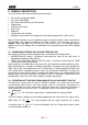
HT4011 4. OPERATING INSTRUCTIONS 4.1. INSTRUMENT DESCRIPTION 4.1.1. Description of the controls CAPTION: 1. Inductive clamp jaw 2. AC voltage detector 3. Rotary selector switch 4. Jaw trigger 5. HOLD key 6. MODE key 7. REL key 8. Hz% key 9. LCD display 10. Input terminal COM 11. Input terminal CAPHz%Temp V Fig.
HT4011 4.2. DESCRIPTION OF FUNCTION KEYS 4.2.1. HOLD key Short pressing the “HOLD” key activates the function Data HOLD, i.e. the value of the measured quantity is frozen. The message “HOLD” appears on the display. This operating mode is disabled when the “HOLD” key is pressed again or the switch is operated. 4.2.2. REL key With the instrument's switch set to positions , , and AC current, this key allows zeroing the displayed value and carrying out a relative measurement of the quantity being tested.
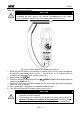
HT4011 4.3. DESCRIPTION OF ROTARY SWITCH FUNCTIONS 4.3.1. DC voltage measurement CAUTION The maximum input DC voltage is 600Vrms. Do not measure voltages exceeding the limits given in this manual. Exceeding these limits could result in electrical shocks to the user and damage to the instrument. 1. 2. 3. 4. 5. Fig. 2: Use of the clamp for DC voltage measurement Select the position. CAPHz%Temp and the black cable into Insert the red cable into input terminal V input terminal COM (Fig. 2).
HT4011 4.3.2. AC voltage measurement CAUTION The maximum input AC voltage is 600V. Do not measure voltages exceeding the limits given in this manual. Exceeding these limits could result in electrical shocks to the user and damage to the instrument. 1. 2. 3. 4. 5. 6. Fig. 3: Use of the clamp for AC voltage measurement Switch on the instrument in any position of selector, near it an AC source and look for the red LED at the clamp's base (see Fig. 1 – Part 2) to turn on.
HT4011 4.3.3. Frequency and Duty Cycle measurement CAUTION When measuring frequency with leads, the maximum input AC voltage is 600Vrms. Do not measure voltages exceeding the limits given in this manual. Exceeding these limits could result in electrical shocks to the user and damage to the instrument. When measuring frequency with the clamp, make sure that all the instrument's input terminals are disconnected. Fig. 4: Use of the clamp for frequency measurement and duty cycle 1.
HT4011 4.3.4. Resistance measurement CAUTION Before attempting any resistance measurement, remove power from the circuit under test and discharge all capacitors, if present. Fig. 5: Use of the clamp for Resistance measurement 1. Select the position 2. Insert the red cable into input terminal V CAPHz%Temp and the black cable into input terminal COM. 3. Position the test leads in the desired points of the circuit to be measured (Fig. 5). The display shows the value of resistance. 4. If the symbol “O.
HT4011 4.3.5. Capacitance measurement CAUTION Before carrying out capacitance measurements on circuits or capacitors, cut off power supply from the circuit being tested and let all capacitance in it be discharged. Fig. 6: Use of the clamp for capacitance measurement 1. Select the CAP position. 2. Press the MODE key cyclically until the symbol “nF” is displayed. 3. Insert the red cable into input terminal V CAPHz%Temp and the black cable into input terminal COM. 4.
HT4011 4.3.6. Continuity test and diode test CAUTION Before attempting any resistance measurement, remove power from the circuit under test and discharge all capacitors, if present. Fig. 7: Use of the clamp for continuity test and diode test 1. Select the position 2. Press the MODE key cyclically until the symbol “ “ is displayed to activate continuity test. 3.
HT4011 4.3.7. Temperature measurement in °C and °F CAUTION Do not put the temperature probe into contact with live surfaces. Voltages higher than 30Vrms or 60VDC imply electrical shock hazard. Fig. 8: Use of the clamp for temperature measurement 1. Select the Temp°C or Temp°F position. 2. Insert the K wire probe provided into input terminal V CAPHz%Temp and COM by means of the relevant adapter, respecting the polarity indicated in Fig. 8. The display shows the value of temperature. 3.
HT4011 4.3.8. AC current measurement CAUTION Before attempting any measurement disconnect all the test leads from the circuit under test and from the meter's input terminals. Fig. 9: Use of the clamp for AC current measurement 1. Select position 40A or 400A 2. Insert the cable in the middle of the clamp jaws, in order to obtain accurate measures. The display shows the value of AC current. 3. If the symbol “O.L” is displayed, this indicates overload status.
HT4011 5. MAINTENANCE 5.1. GENERAL INFORMATION 1. The instrument you purchased is a precision instrument. While using and storing the instrument, carefully observe the recommendations listed in this manual in order to prevent possible damage or danger during use. 2. Do not use the instrument in environments with high humidity levels or high temperatures. Do not expose to direct sunlight. 3. Always switch off the instrument after use.
HT4011 6. TECHNICAL SPECIFICATIONS 6.1. TECHNICAL CHARACTERISTICS Accuracy is calculated as ± [% reading + (number of digits) x resolution]. It is referred to a temperature 18°C 28°C with relative humidity <75% RH. AC Voltage (Autorange) Range Resolution 4,000V 40.00V 400.0V 600V 0,001V 0.01V 0.1V 1V Accuracy (1.8%rdg + 8digits) Input impedance Bandwidth Overvoltage protection 10M 50-400Hz 600V DC/ACrms (2.
HT4011 Frequency with leads (Autorange) Range 10.00Hz 49.99Hz 50.0Hz 499.9Hz 0.500kHz 4.999kHz 5.00kHz 10.0kHz Resolution 0.01Hz 0.1Hz 0,001kHz 0.01kHz Accuracy (1.5%rdg+2digits) Sensitivity Overvoltage protection 15Vrms 600VDC/ACrms Duty cycle (Autorange) Range 0.5% 99.0% Resolution 0.1% Accuracy (1.2%rdg + 2digits) 100s Pulse width 100ms ; Pulse frequency: 100Hz 150kHz; Sensitivity >10Vrms Temperature with K probe (Autorange) Range -20.
HT4011 6.3. ACCESSORIES PROVIDED Pair of 2mm test leads Adapter + K-type wire probe Carrying bag Batteries (not fitted) User manual 6.4. OPTIONAL ACCESSORIES Model Description TK107 Air and gas temperature Internal temperature of semisolid substances Internal temperature of liquids Surface temperature Surface temperature with fixed tip at 90°C TK108 TK109 TK110 TK111 Temperature range Accuracy (at 100°C) Probe length (mm) -40 800 °C ± 2.2rdg 200 Probe diameter (mm) 1.
HT4011 7. SERVICE 7.1. WARRANTY CONDITIONS This instrument is warranted against any material or manufacturing defect, in compliance with the general sales conditions. During the warranty period, defective parts may be replaced. However, the manufacturer reserves the right to repair or replace the product. Should the instrument be returned to the After-sales Service or to a Dealer, transport will be at the Customers charge. However, shipment will be agreed in advance.