
Tus neeg siv phau ntawv


4.3BasicOperation--Single-channelOperation
BeforeconnectingthepowercordtoanAClineoutlet,makesurethatthevoltageselectorontherearpaneloftheinstrument
iscorrectlysetfortheAClinevoltage.Afterensuringthevoltagesetting,Settheswitchesandcontrolsoftheinstrumentas
shownbelow:
15
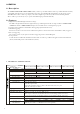
ItemNoSetting
SLOPE(27)+
TRIG.ALT(28)Released
TRIGGERMODE(26)AUTO
TIME/DIV(30)0.5mSec/DIV
SWP.VER(31)CALposition
POSITION(34)Mid-position
Xl0MAG(32)Released
LEVEL(29)Locked
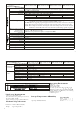
ItemNoSetting
POWER(6)Disengageposition(OFF)
INTEN(2)Mid-position
FOCUS(3)Mid-position
VERTMODE(14)CHl
ALT/CHOP(12)Released(ALT)
CH2INV(16)Released
POSITION(11)(19)Mid-position
VOLTS/DIV(7)(22)0.5V/DIV
VARIABLE(9)(21)CAL(clockwiseposition)
AC-GND-DC(10)(18)GND
SOURCE(24)CHl
Aftersettingtheswitchesandcontrolsasmentioned,connectthepowercordtotheAClineoutlet,andthencontinueasfollows:
1)EngagethePOWERswitchandmakesurethatthepowerLEDisturnedon.Inabout20seconds,atracewillappearon
theCRTscreen.Ifnotraceappearsinabout60seconds,counterchecktheswitchandcontrolsetting.
2)AdjustthetracetoanappropriatebrightnessandimagewiththeINTENcontro1andFOCUScontrolrespectively.
3)AlignthetracewiththehorizontalcenterlineofthegraticulebyadjustingtheCH1POSITIONcontrolandTRACE
ROTATIONcontrol(adjustablebyscrewdriver).
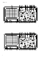
4)ConnecttheprobetotheCH1INPUTterminalandapplythe2Vp-pCALIBRATORsignaltobeprobetip.
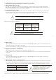
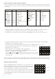
5)SettheAC-GNDDCswitchtotheACstate.Awaveformasshowninthefigure4-3
WillbedisplayedontheCRTscreen.
6)AdjusttheFOCUScontrolsothatthetraceimageappearssharply
7)Forsignalviewing,settheVOLTS/DIVswitchandTIME/DIVswitchinappropriate
positionssothatsignalwaveformisdisplayedclearly.
8)AdjustthePOSITIONandPOSITIONcontrolsinappropriatepositionssothatthe
displayedwaveformisalignedwiththegraticuleandvoltage(Vp-p)andperiod(T)canbe
readconveniently.
Theabovearethebasicoperatingproceduresoftheoscilloscope.Itisforsingle-channeloperationwithCh1.Single-channel
operationwithCH2canalsobeachievedinasimilarmanner.Furtheroperationmethodsareexplainedinthesubsequentpages.
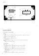
ChangetheVERTMODEswitchtotheDUALstatessothattrace(CH2)isalso
displayed(TheexplanationintheproceedingsectionisofCH1).Atthisstateof
Procedure,theCHltraceisthesquarewaveofthecalibratorsignalandtheCH2
traceisastraightlinesincenosignalisappliedtothischannelyet.
NowapplythecalibratorsignaltotheverticalinputterminalofCH2withthe
probeasisthecaseforCH1.SettheAC-GND-DCswitchtotheACstate.Adjust
verticalPOSITIONknobs(11)and(19)sothatbothchannelsignalsaredisplayed
asshowninFigure4-4
-
.
,
4.4Dual-channelOperation
Figure4-3
Figure4-4
SignalofCH1
16
SignalofCH2