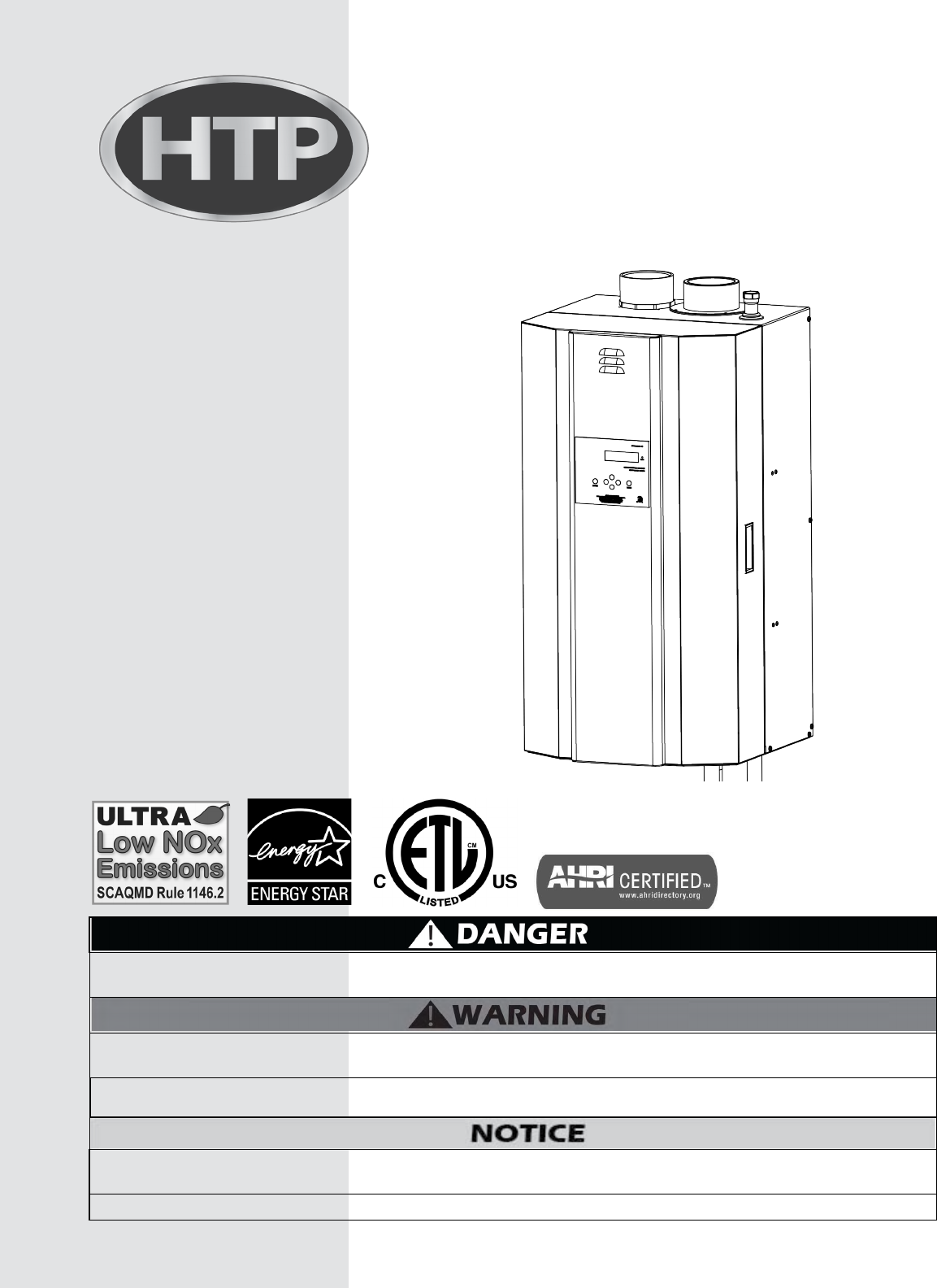
Elite FT Residential and Commercial Models Installation Start-Up Maintenance Parts Warranty EFT-55 / 80 / 110 / 155 / 199 / 285 / 399* Models with 5:1 Turndown Ratio * “LP” Denotes Propane Gas Operation “PU” Denotes Included Pump Heat Exchanger Bears the ASME “H” Stamp This manual must only be used by a qualified installer / service technician. Read all instructions in this manual before installing. Perform steps in the given order.
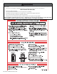
WARNING: If the information in these instructions is not followed exactly, a fire or explosion may result causing property damage, personal injury or death. • Do not store or use gasoline or other flammable vapors and liquids in the vicinity of this or any other appliance. WHAT TO DO IF YOU SMELL GAS • Do not try to light any appliance. • Do not touch any electrical switch; do not use any phone in your building. • Immediately call your gas supplier from a neighbor’s phone.
The following defined terms are used throughout this manual to bring attention to the presence of hazards of various risk levels or to important product information. DANGER indicates an imminently hazardous situation which, if not avoided, will result in serious personal injury or death. WARNING indicates a potentially hazardous situation which, if not avoided, could result in personal injury or death.
The hydronic supply and return connections of these products are for installation in closed loop systems ONLY! Use of this product in any manner other than described in this manual may result in premature product failure, substantial property damage, severe personal injury, or death. Damage or failure of this product (or the system in which it is installed) due to unauthorized use IS NOT COVERED BY WARRANTY.
J. Fill and Purge Heating System K. Glycol Antifreeze Solutions L. Zoning with Zone Valves M. Zoning with Circulators N. Multiple Boilers O. Applications* Part 5 - Venting A. General B. Approved Materials for Exhaust Vent and Intake Pipe C. Additional Requirements for Installation in Canada D. Exhaust Vent and Intake Pipe Location E. Exhaust Vent and Intake Pipe Sizing F. Longer Vent Runs G. Exhaust Vent and Intake Pipe Installation H. Applications 19 19 20 20 20 21 28 28 29 29 30 31 31 31 32 C.
exchanger. Such damage IS NOT covered by warranty. Do not use this boiler for anything other than its intended purpose (as described in this manual). Doing so could result in property damage and WILL VOID product warranty. Due to the low water content of the boiler, improper sizing of the boiler with regard to heating system load will result in excessive cycling and accelerated component failure. HTP DOES NOT warrant failures caused by improperly sized boiler applications.
The control can be set to monitor outdoor temperature through an outdoor sensor to regulate boiler set point. The system can be further enhanced by installing an indirect water heater to provide domestic hot water. The control can regulate the output of multiple boilers through its cascade system function. The cascade system is capable of connecting up to eight boilers together in such a way that they function as one boiler system.
This boiler must be installed upright in the vertical position as described in this manual. DO NOT attempt to install this boiler in any other orientation. Doing so will result in improper boiler operation and property damage, and could result in serious personal injury or death. Failure of the boiler or components due to incorrect operating conditions IS NOT covered by product warranty. Figure 2 - Boiler Mounted to Mounting Bracket on Pallet A.
Figure 3 - Recommended Service Clearances Minimum Clearances from Combustible Materials • Hot water pipes - at least 1” from combustible materials • Exhaust vent pipe - at least 1” from combustible materials Do not mount the boiler to a hollow wall. Mount to the studs only. Use extreme care not to drop the boiler or cause bodily injury while lifting or mounting the boiler onto the wall mount bracket.
2. Mounting to a Metal Frame a. The provided mounting bracket must be mounted to the center of at least 2 studs using standard steel or stainless steel toggle bolts 3/16” diameter or larger, and at least 2” long for direct mounting on stud for 55 – 110 models, and 3/8” diameter or larger, and at least 2” long for 155 – 399 models for direct mounting on at least 18 gauge Figure 4 - Wall Mounting Bracket - NOTE: Drawing for Demonstration studs.
Failure to vent the boiler properly will result in serious personal injury or death. Do not attempt to vent this boiler by any means other than those described in this manual. Doing so will void the warranty and may result in severe personal injury or death. Vents must be properly supported. Boiler exhaust and intake connections are not designed to carry heavy weight. Vent support brackets must be within 1’ of the boiler and the balance at 4’ intervals.
Areas Products to Avoid Spray cans fluorocarbons Likely to Have Contaminants containing Dry cleaning / laundry areas and establishments Permanent wave solutions Swimming pools Chlorinated waxes / cleaners Metal fabrication plants Chlorine-based swimming pool Beauty shops chemicals Calcium chloride used for thawRefrigeration repair shops ing Sodium chloride used for water Photo processing plants softening Figure 5 - CO Warning Label K.
• Hardness less than 7 grains (120 mg/L) (Water temperatures of 140oF and greater) • Hardness levels above the required amounts can lead to lime scale build-up throughout the system. Water below 5 grains/gallon (85 mg/L) may be over softened. • Consult local water treatment companies for unusually hard water areas (above the required amounts) or for other treatment solutions if water is being over softened (below 5 grains/gallon [85 mg/L]).
M.
Figure 6 - Boiler Dimensions - NOTE: All Dimensions Are Approximate LP-387 Rev. 011 Rel. 006 Date 6.28.
Part 4 - Piping Failure to follow the instructions in this section WILL VOID the warranty and may result in property damage, severe personal injury, or death. The National Standard Plumbing Code, the National Plumbing Code of Canada, and the Uniform Plumbing Code limit heat transfer fluid pressure to less than the minimum working pressure of the potable water system up to 30 PSI maximum.
D. Potable Expansion Tank F. Hydronic Piping with Circulators, Zone Valves, and Expansion Tank and Make-Up Water Multiple Boilers 1. Ensure that the expansion tank is sized to correctly handle boiler This boiler is designed to function in a closed loop hydronic system. and system water volume and temperature. It is recommended to install a temperature and pressure gauge (not included with the boiler) to allow the user to monitor system pressure and outlet temperature from the boiler.
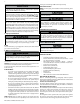
Figure 7 - Boiler Pressure Drop The chart below represents various system design temperature rise through the boiler along with respective flows and friction loss. This is provided to aid in circulator selection. System Temperature Rise Chart 20°Δt 25°Δt 30°Δt Model Friction Ft Flow Rate (GPM) Friction Ft Flow Rate (GPM) Friction Ft Flow Rate (GPM) 55 1.8’ 5.3 1.1’ 4.2 0.8’ 3.5 80 2.8’ 8.2 1.9’ 6.5 1.3’ 5.4 110 4.3’ 10.6 2.9’ 8.4 1.8’ 7 155 2.5’ 14.6 1.7’ 11.7 1.
H. Check / Control Water Chemistry NOTE: Boiler failure due to improper water chemistry is not covered by warranty. • Water pH between 6.5 and 8.5 • Hardness less than 7 grains (120 mg/L) (Water temperatures of 140oF and greater) • Chloride concentration less than 100 ppm (mg/L) • Total Dissolved Solids (TDS) less than 500 ppm (mg/L) *NOTE: It is recommended to clean the heat exchanger at least once a year to prevent lime scale buildup.
• • • • • Glycol in hydronic applications should include inhibitors that prevent the glycol from attacking metallic system components. Make certain that the system fluid is checked for the correct glycol concentration and inhibitor level. The glycol solution should be tested at least once a year or as recommended by the glycol manufacturer. Anti-freeze solutions expand more than water. For example: A 50% by volume solution expands 4.
O. Applications* Mixing valves are required for the protection of low temperature loops. Figure 8 - Near Boiler Piping* - NOTE: This drawing is meant to show system piping concept only. Installer is responsible for all equipment and detailing required by local codes. *Top / Bottom Supply / Return Connections Available on 155 / 199 / 285 / and 399 Models ONLY.
Figure 9 - Piping Symbol Legend LP-387 Rev. 011 Rel. 006 Date 6.28.
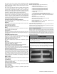
Figure 10 - Standard Piping with Zone Valves and Indirect Priority NOTES: 1. This drawing is meant to show system piping concept only. Installer is responsible for all equipment and detailing required by local codes. 2. All closely spaced tees shall be within 4 pipe diameters center to center spacing. 3. A minimum of 6 pipe diameters of straight pipe shall be installed upstream and downstream of all closely spaced tees. 4. The minimum pipe size for connecting an indirect water heater is 1” 5.
Figure 11 - Standard Piping with Pumps and Indirect Priority NOTES: 1. This drawing is meant to show system piping concept only. Installer is responsible for all equipment and detailing required by local codes. 2. All closely spaced tees shall be within 4 pipe diameters center to center spacing. 3. A minimum of 6 pipe diameters of straight pipe shall be installed upstream and downstream of all closely spaced tees. 4. The minimum pipe size for connecting an indirect water heater is 1” 5.
Figure 12 - Primary / Secondary Piping with Zone Valves and Indirect Priority NOTES: 1. This drawing is meant to show system piping concept only. Installer is responsible for all equipment and detailing required by local codes. 2. All closely spaced tees shall be within 4 pipe diameters center to center spacing. 3. A minimum of 6 pipe diameters of straight pipe shall be installed upstream and downstream of all closely spaced tees. 4.
Figure 13 - Primary / Secondary Piping with Pumps and Indirect Priority NOTES: 1. This drawing is meant to show system piping concept only. Installer is responsible for all equipment and detailing required by local codes. 2. All closely spaced tees shall be within 4 pipe diameters center to center spacing. 3. A minimum of 6 pipe diameters of straight pipe shall be installed upstream and downstream of all closely spaced tees. 4. The minimum pipe size for connecting an indirect water heater is 1” 5.
If boiler supply temperature for DHW is set higher than central heating, the heating circuit must be protected by a thermostatic mixing valve. Figure 14 - Multiple Boilers - Primary / Secondary Piping with Pumps and Indirect Priority NOTES: 1. This drawing is meant to show system piping concept only. Installer is responsible for all equipment and detailing required by local codes. 2. All closely spaced tees shall be within 4 pipe diameters center to center spacing. 3.
Part 5 - Venting The boiler must be vented as detailed in this section. Ensure exhaust vent and intake piping complies with these instructions regarding vent system. Inspect finished exhaust vent and intake piping thoroughly to ensure all joints are well secured, airtight, and comply with all applicable code requirements, as well as the instructions provided in this manual. Failure to properly install the vent system will result in severe personal injury or death. A.
B.
D. Exhaust Vent and Intake Pipe Location INSIDE CORNER DETAIL G E A H E B B E OPERABLE C FIXED CLOSED FIXED CLOSED D E E I E OPERABLE F M I B E E K E I E B J A K I B L LP-179-CC 03/28/17 E Exhaust Vent Terminal I Intake Pipe Terminal Area Where Intake Terminal Is Not Permitted Figure 15 - Exit Terminals for Direct Vent Systems - ANSI Z223.1 / NFPA 54 for US and CAN/CSA B149.
E. Exhaust Vent and Intake Pipe Sizing 1. The exhaust vent and intake pipe size is 3” for 55 - 285 models and 4” for the 399 model. 2. The maximum total equivalent length of exhaust vent and intake pipe should not exceed 200 feet for all models EXCEPT the 285 model. Total equivalent length for the 285 model should not exceed 150 feet. a. The equivalent length of elbows, tees, and other fittings are listed in the Friction Loss Table.
instructions reference snow levels in establishing a minimum height for the installation of exhaust vent or air intake terminations. Snow levels shall be determined as follows: a. The installation location may, by ordinance, designate how snow levels are calculated in that location; or b.
Take extra precaution to adequately support the weight of vent pipes terminating through the roof. Failure to properly support roof terminated piping could result in property damage, serious injury, or death. Sidewall Venting with Kit VENT KIT EXTERIOR WALL TWO PIPE ROOF VENTING WITH TEE (INTAKE) AND COUPLING (EXHAUST) STRAIGHT COUPLING EXHAUST INSERT INLET/EXHAUST SCREEN INTO STRAIGHT COUPLING 24" MIN.
Intake Exhaust 24.00 LP-325-OO 02/04/15 EXHAUST A AIR INTAKE B FRONT VIEW Figure 20 - Unbalanced Venting - Roof Exhaust and Sidewall Intake NOTE: These drawings are meant to demonstrate system venting only. The installer is responsible for all equipment and detailing required by local codes.
Contractors must check state and local codes before installing through an existing vent opening. State and local codes always take precedence over manufacturer’s instructions. Failure to check state and local codes before installing through an existing opening could result in property damage and add significantly to installation costs.
EXHAUST Indoor Combustion Air (Single Pipe) ROOM OPENING DO NOT INSTALL WATER HEATER, BOILER, OR APPLIANCE NEAR DRYER Boiler, Water Heater, or Appliance ROOM OPENING 6" Outdoor Combustion Air (Single Pipe) Figure 22 - Do Not Place Appliance Near Dryer 6" LP-325-S 09/29/11 EXHAUST LP-325-X UPPER AIR DUCT Boiler, Water Heater, or Appliance LOWER AIR DUCT LP-325-T 8/5/2010 Figure 23 - Indoor and Outdoor Combustion Air - Single Pipe LP-387 Rev. 011 Rel. 006 Date 6.28.
Part 6 - Condensate Removal NOTE: Check with your local gas company to determine if combustion condensate disposal is permitted in your area. In the state of Massachusetts, condensate must be neutralized before entering a drain. This boiler is a high efficiency appliance, and therefore produces condensate: a by-product of the combustion process. A condensate collection system with an internal float switch monitors condensate level to prevent it from backing up into the combustion system.
Condensate Neutralization Condensate from the boiler is slightly acidic with a pH of 3.2 - 4.5. To avoid long term damage to the drainage system and to meet local code requirements, HTP recommends neutralizing the condensate with a Condensate Neutralizer Kit (Part # 7450P-212). The neutralizer kit connects to the drain system and contains limestone chips that neutralize the pH level of the water vapor. The neutralizer kit should be checked annually and the limestone chips replenished if necessary.
Part 7 - Wiring Power to the optional condensate pump is continuous. When the boiler is powered off the condensate pump will remain on. It is important to remember to turn off the condensate pump when powering down the boiler. Failure to do so could result in property damage, severe personal injury, or death. The condensate line must remain unobstructed.
If the boiler is configured as a cascade master, the system pump output is a dry contact output capable of switching 5 amps at 120 volts, in addition to the boiler pump output sourcing 4 amps each. The electrical junction box has separate, clearly marked terminal strips for line voltage and low voltage wiring. Special jacks are provided for trouble-free cascade system wiring using standard CAT3 or CAT5 patch cables.
2. Connect the indirect sensor (7250P-325) to the terminals marked Follow the complete instructions included in the kit for proper DHW SENSOR (shown in Figures 29 and 32) in the electrical junction installation. box. NOTE: The control system senses system water temperatures entering and exiting the heat exchanger to provide protection against low water conditions.
5. Connect the boilers in a daisy chain configuration as shown below. It is best to wire the boilers using the shortest wire runs rather than trying to wire them in the order that they are addressed. The communication bus jacks on the customer connection panel are interchangeable so you can use either one or both in any order to connect the cable. If you have connected the boilers to each other properly, there will be no open communication connection ports. M. Cascade Master Pump and Sensor Wiring 1.
Figure 33 - Internal Connection Diagram LP-387 Rev. 011 Rel. 006 Date 6.28.
Part 8 - Gas Connections Failure to follow all precautions could result in fire, explosion, severe injury, or death. It is very important that you are connected to the type of gas noted on the rating plate. “LP” for liquefied petroleum, propane gas, or “NG” for natural or city gas. Do not do a gas conversion without an approved gas conversion kit. Prior to turning the gas on, all gas connections must be approved by the local gas supplier or utility, in addition to the governing authority.
Use two wrenches when tightening gas piping at the boiler: One to prevent the boiler gas line from turning. Failure to prevent the boiler gas connection from turning could result in damage to the gas line components, substantial property damage, severe personal injury, or death. CSA or UL listed flexible gas connections can be used when installing the boiler. Flexible gas connections have different capacities and must be sized correctly for the connected boiler firing rates.
C. Boiler Gas Valve discontinue use of the appliance and contact an authorized technician or licensed professional. • • Water pH between 6.5 and 8.5 Hardness less than 7 grains (120 mg/L) (Water temperatures of 140oF and greater) • Chloride concentration less than 100 ppm (mg/L) • Total Dissolved Solids (TDS) less than 500 ppm (mg/L) *NOTE: It is recommended to clean the heat exchanger at least once a year to prevent lime scale buildup.
D. Fill and Test Water System Ensure the boiler is full of water before firing the burner. Failure to do so will damage the boiler. Such damage IS NOT covered by warranty, and could result in property damage, severe personal injury, or death. 1. Fill the system only after ensuring water chemistry meets the requirements listed in this manual. 2. Close the manual and automatic air vents and boiler drain valve. 3. Fill to the correct system pressure. Correct pressure will vary with each application. a.
2. Verify the boiler and system are full of water and all system required temperature, the master boiler control will then tell the next boiler in the firing sequence to begin its demand sequence. The master components are correctly set for operation. boiler control will then begin to ramp up the firing rate command of that boiler.
Example: In a 2 boiler system with an indirect connected to the follower, the follower address would be 2 (address 1 is not B. Navigation of the Display The display includes a two line backlit LCD readout to provide used). informative messages about the operation of the boiler. Many a. Make sure there is no demand for heat being supplied to the operating parameters can be viewed and adjusted by using the six master boiler buttons on the display. The function of each button is described b.
the boiler, such as the tank thermostat, is turned off, so the boiler will remain idle to allow programming. Screen Description ENTER MENU CODE 000 To access the boiler setting program, press and hold ENTER for 4 seconds until the display shows the screen at left. ENTER MENU CODE 600 Use the arrow keys to log in the Boiler Menu Access Code - 600. Press ENTER to confirm the code and access the Boiler Setting Program navigation menu. CLOCK YEAR 08/28/2009 Fr 10:01A Adjusts the year setting.
Screen Description Function 7 Warm Weather Shutoff When used with an outdoor sensor, warm weather shut down will disable WARM WEATHER OFF the boiler if the programmed outdoor 68 oF 7 temperature is exceeded. Default: 68oF (Range: 41oF to 122oF). Function 8 Min Outdoor Temp MIN OUTDOOR TEMP 5 oF 8 Not applicable on this product. Function 9 Max Supply Temp MAX SUPPLY TEMP 190 oF Sets the maximum design supply temperature based on the minimum outdoor design temperature.
Screen Description Function 28 FREEZE PROTECTION ON Freeze Protection Allows the user to set freeze protection on the boiler. Factory Default: ON 28 (Range: ON / OFF). Function 29 DHW Modulation Mode DHW MODULATE MODE NORMAL MOD 29 This parameter controls how the boiler modulates for a DHW demand. In NORMAL MOD mode, the boiler will modulate down from high fire when there is a DHW demand. In LOW MOD mode, the boiler will modulate up from low fire when there is a DHW demand.
Screen Part 11 - Start-Up Procedures for the Installer CENTRAL HEATING CURVE Factory Default 212 201˚ SUPPLY SEN RETURN SEN 203 194 185 FUNCTION 9 176 158 DEFAULT RESET CURVE 149 131 CH SET SUPPLY SEN 122 113 104 95 77 FUNCTION 10 FUNCTION 11 86 FUNCTION 8 SUPPLY OUTLET TEMPERATURE (F) This is the first screen that appears after pressing >, and shows the actual temperatures measured by the supply o 180 F and return sensors.
The top line displays the voltage on 0.0V the optional input. This voltage is only relevant if an external 0-10 volt signal is being used to control the boiler. 0-10 V BOILER Press v once. BUS COMM This display shows the status of the communication bus between multiple boilers. If in a single boiler configuration, the display will show NO CONN ‘NO CONN’.
This screen displays overall cascade power output. The range of this value is This menu is accessed by pressing < at the default menu or > at the the number of boilers communicating status menu. with the Master x 100. For example, CASCADE PWR 100% Screen Description if 8 boilers are connected and firing, PRESENT 01234567 the maximum cascade power is 800%.
Combustion Settings on All Models Fan Speed Natural Gas (NG) Propane (LP) Low Ignition High Low Ignition High Carbon Monoxide (CO) PPM 5-50 <175 5-50 60-100 <175 Carbon Dioxide (CO2) % 8-10 9-10 1/2 9 1/2-11 60-100 8 1/2-10 1/2 Table 27 - Combustion Settings - All Models Fan Speeds BTU Ignition 55,000 80,000 Min Max 1700 4050 3800 110,000 5000 1850 155,000 4100 199,000 3800 1750 285,000 4600 1800 399,000 4200 2500 6050 5400 6050 6950 Table 28 - Fan Speeds Part
D. User Interface Display Cascade Control Fault Codes Screen Description Possible Remedy SYS SUPPLY SENSOR PUMP OFF E03 E03 indicates a problem with the system sensor circuit. The circuit could be open or shorted. Possible reasons for this error are: There is no system sensor connected to the Master Boiler. The system sensor is faulty. There is a short circuit in the system sensor wiring; possibly from a staple placed through the wire, or damage to the wire causing both conductors to touch.
LOU indicates the 24 volt power supply on the control is damaged or overloaded. This code resets automatically if it is the result of an overload and the overload condition is removed. The second line indicates the status of the pump. Note that while 24 volt power is low, the pump output will be on. 1. Check line voltage. It must be between 100 and 128 volts. 2. If available, connect a PC and use HTP service software to check the 24v supply display in the lower left corner of the screen.
RETURN SENSOR F03 PUMP ON F03 indicates the return temperature sensor of the boiler has failed. The boiler will not restart until a technician replaces the sensor and pushes RESET on the display. This is a serious safety issue as indicated by the illuminated red light and the word LOCKOUT flashing on the display. During this lockout fault, the pump will be on. 1. Check circulator pump operation. 2.
1. Watch the igniter through the observation window. 2. If there is no spark, check the spark electrode for the proper .156” (3.96 mm) gap. See below. 3. Remove any corrosion from the spark electrode and flame rectifier probe. 4. If there is a spark but no flame, check the gas supply to the boiler. 5. If there is a flame, check the flame sensor. 6. Check any flue blockage or condensate blocks.
FAN SPEED ERROR F13 PUMP ON The fan is not running at the speed determined by the control. Fan speed has been more than 30% faster or slower than the commanded speed for more than 10 seconds. This is a serious safety issue as indicated by the illuminated red light and the word LOCKOUT flashing on the display .This boiler will not restart until a technician determines and repairs the cause and pushes RESET on the display. During this lockout fault, the pump will be on.
b. Connect the thermostat wires to the field connection board, or turn up thermostat to fire the combustion system. Check for leaks in the combustion system. Observe operation for 5 to 10 A. Procedures minutes. Periodic maintenance should be performed once a year by a qualified If boiler is operating properly, condensate is flowing normally, and service technician to assure that all the equipment is operating safely no gas leaks are detected, combustion coil cleaning is complete. and efficiently.
C. Cleaning Water Side of Heat Exchanger 1. Make sure power is turned off to the boiler. Run water through the hot water system to ensure it is below room temperature. 2. Close isolation valves on the return and supply connections to the boilers as shown in the piping diagrams in this manual. Slowly open the ball valves and release pressure into a bucket. Once pressure is released, connect a hose to the water line to flush the boiler.
D. Important Notice Do not operate the boiler without the clear hose attached from the hose barb to the pressure switch. Failure to follow this warning could result in property damage, serious personal injury, or death. 10. If a condensate neutralizer kit is installed with the boiler, check the assembly when cleaning the condensate trap, and replenish the limestone chips if necessary.
Part 15 - Installation Checklist Light Off Activities Date Completed: Check all piping and gas connections. Verify all are tight. Pressurize system. (12 - 15 psi) 1. Fill the Heating System PSI Add water to prime condensate cup. Percentage of glycol in system (0 - 50%) % Verify near boiler piping is properly supported. Leak test using locally approved methods (consult jurisdictional code book). 2. Check Gas Pipe Check incoming gas pressure (3.5 to 14” WC).
Inspection Activities Piping Near boiler piping Check boiler and system piping for any sign of leakage; make sure pipes are properly supported. Vent Check condition of all vent pipes and joints. Ensure the vent piping terminations are free of obstructions and blockages. System Visual Do a full visual inspection of all system components. Functional Test all functions of the system (Heat, Safeties).
Part 17 - Replacement Parts Figure 37 - Combustion System Replacement Parts - 55 - 110kBTU Models LP-387 Rev. 011 Rel. 006 Date 6.28.
See Chart Figure 38 - Replacement Parts - 55 - 110kBTU Models - *#20 - Switch on the Left is the Blocked Flue Pressure Switch on the Right is the Blocked Condensate Pressure Switch - Both share same Part Number LP-387 Rev. 011 Rel. 006 Date 6.28.
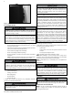
2 1 3 4 5 6 23 7 22 8 21 9 24 11 20 10 12 13 19 14 18 17 15 16 ITEM 155 1 7500P-031 199 7350P-159 2 DESCRIPTION COMBUSTION BLOWER (w/GASKET) 7 5 0 0 P -0 7 5 G A SK E T - C O M BUSTIO N BLO W E R 3 7600P-908 7600P-909 AIR CHANNEL (w/GASKET, SCREWS) 4 7600P-105 7600P-106 GASKET - BURNER 5 7600P-155 7600P-114 6 7600P-115 BURNER (w/GASKET) FLAME RECTIFICATION PROBE (w/GASKET, SCREWS) 7 6 0 0 P -0 8 7 7 7 3 5 0 P -0 2 1 IG N ITO R ( w / G A SK E T, SC R E W S) 8 7600P-91
See Chart Figure 40 - Replacement Parts for all 155 and 199kBTU Models, and 285 - 399kBTU Models Manufactured BEFORE 10/29/17 - *#15 - Switch on the Left is the Blocked Flue Pressure Switch on the Right is the Blocked Condensate Pressure Switch - Both share same Part Number LP-387 Rev. 011 Rel. 006 Date 6.28.
Model Control Board Part Numbers Model Control Board Part Numbers 55kBTU 7600P-1100 199kBTU 7600P-1104 80kBTU 7600P-1101 285kBTU 7600P-1105 110kBTU 7600P-1102 399kBTU 7600P-1106 155kBTU 7600P-1103 Table 33 - Control Board Part Numbers LP-387 Rev. 011 Rel. 006 Date 6.28.
Elite FT Boiler Limited Warranty Twelve year warranty to assure your complete satisfaction. HTP warrants this boiler and its components to be free from defects in material and workmanship according to the following terms, conditions, and time periods. UNLESS OTHERWISE NOTED THESE WARRANTIES COMMENCE ON THE DATE OF INSTALLATION. This limited warranty is only available to the original consumer purchaser (herinafter “Owner”) of this boiler, and is non-transferable.
installation, failure to operate the boiler at firing rates or pressures not exceeding those on the rating plate, or failure to operate and maintain the boiler in accordance with the manufacturer’s provided instructions. 13. Failure to operate the boiler in a closed system with a properly sized and installed thermal expansion tank. 14.
Maintenance Notes LP-387 Rev. 011 Rel. 006 Date 6.28.
Customer Installation Record Form The following form should be completed by the qualified installer / service technician for you to keep as a record of the installation in case of a warranty claim. After reading the important notes at the bottom of the page, please also sign this document.