
Instruction Manual


54
LP-387 REV. 6.10.14
D. LINE VOLTAGE WIRING FOR STANDARD BOILER
NOTE: A termination plug is included in the CAT 3 / CAT 5 Bus Connection Point, labeled J3 in Figure 23. DO NOT REMOVE THIS
PLUG! Doing so will affect boiler operation and void warranty.
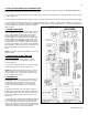
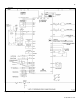
1. Connect the incoming power wiring to the line voltage terminal strip in the electrical junction box at terminals 120V, Neutral, Ground
(shown in Figure 31).
2. A line voltage fused disconnect switch may be required, externally mounted and connected according to local codes that may apply.
3. Connect the boiler pump as shown in Figure 31 to the terminals marked 1 – (HOT), 2 – (NEUT), and 3 – (GND). The connections
shown are suitable for a maximum continuous pump draw of 3 amps at 120 volts. If the pump requires more current or voltage than the
120 volts supplied, an external motor starter or contactor
will be required.
E. ALARM CONNECTIONS
The control includes a dry contact alarm output. This is an
SPDT circuit, rated at 5 amps at 120 volts. This contact
can be used to activate an alarm light or bell or notify a
building management system if the boiler goes into a
lockout condition. The circuit between the ALARM COM
and NC terminals is closed during normal operation and
the circuit between ALARM COM and NO is open during
normal operation. The connections depicted in Figure 31
show two 120 volt lights connected to the alarm terminals.
One light will be on when the boiler is in normal mode and
the other light will be on when the boiler is in lockout
mode.
NOTE: Isolate 120V wiring from 24V wiring to prevent any
electrical “noise”.
F. LOW VOLTAGE CONNECTIONS FOR
STANDARD BOILER
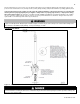
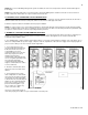
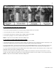
1. All low voltage cables should enter the electrical
junction box through the provided knock out holes as
shown in Figure 30.
2. Connect all low voltage field devices to the low voltage
terminal strip located in the electrical junction box.
NOTE: When making low voltage connections, ensure no
external voltage is present in the thermostat circuits. If
external voltage is present, provide an isolated contact to
prevent damage to the control.
G. THERMOSTAT
1. Connect the room thermostat to the terminals marked
THERMOSTAT in the electrical junction box (see Figure
31). Alternately, any dry contact closure across these
terminals will cause the boiler to run. Take caution to
ensure neither of the terminals becomes connected to
ground.
2. Mount the thermostat on an inside wall as central as
possible to the area being heated, but away from drafts or
heat producing devices such as television sets that could
influence the ability of the thermostat to measure room
temperature.
3. If the thermostat is equipped with an anticipator and it is
connected directly to the boiler, the anticipator should be
set at 0.1 amps. If the thermostat is connected to other
device(s), the anticipator should be set to match the power
requirements of the device(s). See the instruction manual
of the connected device(s) for further information.
Figure 31 – Boiler Control