
Instruction Manual


57
LP-387 REV. 6.10.14
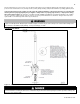
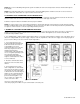
Figure 33 – Cascade Resistor Plug Installation Detail
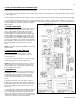
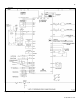
M. CASCADE MASTER PUMP AND SENSOR WIRING
1. Connect the system pump hot wire to the terminal marked 8.
2. Connect the system pump neutral to the 2 terminal and the pump ground wire to the 3 terminal.
3. Connect a jumper wire from the 120 VOLT terminal to the 9 terminal.
4. Connect the boiler pump to the terminals marked 1 (HOT), 2 (NEUT) and 3 (GND).
5. Connect the system pipe sensor to the terminals marked 10 and 11.
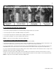
NOTE: See Figure 32 for Cascade Master and Follower Wiring detail.
N. CASCADE FOLLOWER PUMP AND SENSOR WIRING
1. Connect the boiler pump to the terminals labeled 1 (HOT), 2 (NEUT), and 3 (GND).
2. An alarm bell or light can be connected to the alarm contacts of the follower boiler. The normally closed alarm contact may be used
to turn a device off if the boiler goes into lockout mode. The alarm contacts are rated 5 amps at 120 VAC.
To connect an alarm device, connect the power for the device to the ALARM COM terminal. Connect the alarm device hot wire to the
ALARM NO terminal. Connect the neutral or return of the alarm device to the neutral or return of the power for the alarm device.
To connect a device that should be powered off during a boiler lockout condition, follow the same instructions as above except use the
ALARM NC terminal rather than the ALARM NC terminal.
Note that in a cascade system the alarm output of the boiler addressed as #1 will also be active if the master boiler has a lockout
condition. The alarm output of boilers addressed as 2-7 will only activate an alarm if a lockout condition occurs on that specific boiler.
NOTE: See Figure 34 for Cascade Master and Follower Wiring detail.