
Instruction Manual


75
LP-387 REV. 6.10.14
SCREEN
DESCRIPTION
POSSIBLE REMEDY
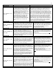
Fault Code F01
FLUE TEMP/WAT LV F01
PUMP ON
This display indicates that the flue temperature
limit switch of the boiler has tripped or that the
water level in the boiler is low (this will only occur
if the optional UL353 LWCO is installed). This
code indicates a serious safety issue. The boiler
will not restart until the flue cools down
sufficiently or the water level is restored. A tech-
nician must repair the cause of the problem and
push the RESET button first on the low water
cut-off control box, then on the display. This
situation is indicated by the red light on the
display and the word LOCKOUT flashing on the
display. During this lockout fault, the pump will
be on as indicated on the second line of the
display.
1. If the boiler has a UL353 LWCO, check if the red LED on the
LWCO control box is illuminated. If so, correct the low water con-
dition and press the reset button on the LWCO control box to reset
the LWCO. The LED should change to green. Press the reset
button on the front panel of the boiler to reset the boiler control.
2. Check the flue for obstructions or any sign of damage, especially
signs of excessive heat. Repair as necessary. Push the red reset
button on the flue temperature switch located on the flue inside the
rear access door of the boiler. NOTE: The switch temperature must
be less than 90°F to reset. Press the reset button on the display.
Run the boiler and check the flue temperature by using both an
external thermometer in the flue pipe and the flue temperature
display in the status screens. If the flue temperature is within specs
and the switch trips, replace the switch. If the flue temperature is
excessive, check and adjust combustion controls on the boiler. If
the problem persists, inspect the target wall in the combustion
chamber and replace it if cracked or damaged.
Fault Code F02
SUPPLY SENSOR F02
PUMP ON
Indicates that the supply temperature sensor of the boiler
has failed. This is a serious safety issue and the boiler will
not restart until the sensor is replaced by a technician and
he pushes the RESET button on the display. This situation
is indicated by the red light on the display and the flashing
word LOCKOUT. During this lockout fault, the pump will be
on as indicated on the second line of the display.
1. Check the electrical connection to the thermistor on
the outlet manifold. Verify 5 VDC by checking in Molex
connector. If there is no 5 VDC, check the harness. If
harness is OK, replace control. NOTE: The boiler will
reset automatically. Verify thermistor values by
referencing chart in this manual.
2. Replace thermistor if necessary.
Fault Code F03
RETURN SENSOR F03
PUMP ON
This display indicates that the return temperature sensor of
the boiler has failed. This code indicates a serious safety
issue and the boiler will not restart until the sensor is
replaced by a technician and he pushes the RESET button
on the display. This situation is indicated by the red light on
the display and the word LOCKOUT flashing on the display.
During this lockout fault, the pump will be on as indicated on
the second line of the display.
1. Check circulator pump operation.
2. Assure that there is adequate flow through the boiler
by accessing the status menu and assuring that there is
less than a 50°F rise from the return thermistor to the
supply thermistor.
3. Troubleshoot thermistor by following steps in F02.
Fault Code F04
FLUE SENSOR F04
PUMP ON
This display indicates that the flue temperature sensor of the
boiler has failed. This is a serious safety issue. The boiler will
not restart until the sensor is replaced by a technician and he
pushes the RESET button on the display. This situation is
indicated by the red light and the flashing word LOCKOUT on
the display. During this lockout fault, the pump will be on as
indicated on the second line of the display.
Inspect the flue sensor for physical damage or
corrosion and replace it if necessary. Check the
electrical connection to the flue sensor and repair as
necessary. Measure the resistance of the sensor and
refer to the Supply Temperature Sensor chart in Table
29 of this manual. The temperature on the chart
should be close to the same as the temperature in the
flue. If not, replace the flue sensor.
Fault Code F05
SUPPLY TEMP HIGH F05
PUMP ON
This display indicates that the supply temperature of the boiler
is excessive. If accompanied by the red FAULT light and
LOCKOUT flashing on the display, this code indicates that the
temperature on the supply sensor has exceeded 230
o
F and a
serious safety issue exists. The boiler will not restart until the
cause of the excessive temperature is repaired by a technician
and the RESET button is pushed on the display.
If the FAULT light is not illuminated and this message is
displayed, then the supply temperature of the boiler is at or
above 210
o
F. The message will clear automatically when the
temperature drops below 194
o
F. During the time that this
message or lockout fault is displayed, the pump will be on as
indicated on the second line.
1. Check circulator pump operation.
2. Assure that there is adequate flow through the
boiler by accessing the status menu and assuring that
there is less than a 50°F rise from the return
thermistor to the supply thermistor.
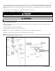
3. Check the direction of flow off the boiler circulator.
(See Piping Details in this manual.)
4. Troubleshoot the thermistor by following steps in
F02.
Fault Code F06
RETURN TEMP HIGH F06
PUMP ON
This display indicates that the return temperature of the
boiler is excessive. If accompanied by the red FAULT light
and LOCKOUT flashing on the display, the return sensor
temperature has exceeded 230
o
F and a serious safety issue
exists. The boiler will not restart until the cause of excessive
temperature is repaired by a technician and the boiler is
RESET.
If the red FAULT light is not illuminated, then the return tem-
perature of the boiler is at or above 210
o
F. The message will
clear automatically when the temperature drops below 194
o
F. During the time that this message or lockout fault is dis-
played, the pump will be on as indicated on the second line.
1. Check circulator pump operation.
2. Assure that there is adequate flow through the boiler
by accessing the status menu and assuring that there is
less than a 50°F rise from the return thermistor to the
supply thermistor.
3. Check the direction of flow on boiler circulator. (See
Piping Details in this manual.)
4. Troubleshoot thermistor by following steps in F02.