
Manual

52
LP-171 Rev. 4.10.14
Strain on the gas valve and fittings may result in vibration, premature component failure and gas leakage, and result in fire, explosion,
property damage, severe personal injury, or death.
Adjustments to the throttle screw or offset may only be made by a qualified gas technician using a calibrated combustion analyzer
capable of measuring CO
2
and CO. Failure to follow this instruction could result in fire, explosion, property damage, severe personal
injury, or death.
PART 9 – FIELD WIRING
ELECTRICAL SHOCK HAZARD – Turn off electrical power supply at service entrance panel before making any electrical connections.
Failure to do so can cause severe personal injury or death.
Wiring must be N.E.C. Class 1. If original wiring supplied with the heater must be replaced, use only UL Listed TEW 105
o
C wire or
equivalent. Heater must be electrically grounded as required by National Electrical Code ANSI/NFPA 70 – Latest Edition.
In order to ease future servicing and maintenance, it is advised to label all wires. Wiring errors can cause improper and dangerous
operation. Failure to follow these instructions could result in property damage or personal injury.
A. INSTALLATION MUST COMPLY WITH:
National Electrical Code and any other national, state, provincial or local codes or regulations.
In Canada, CSA C22.1 Canadian Electrical Code Part 1, and any local codes.
B. FIELD WIRING
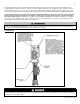
For your convenience we have located the electrical connection of the heater on the front right hand side of the unit. The electrical junc-
tion box has a 24 volt terminal compartment and 120 volt terminal compartment. Each terminal connection is clearly marked to assure
correct installation.
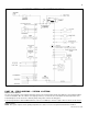
C. LINE VOLTAGE WIRING
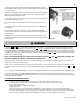
1. Connect 120 VAC power wiring to the line voltage terminal strip located inside the electric junction box, as shown in Figure 30.
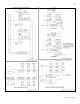
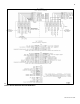
2. Wire the Heater Primary Circulator (P1) to the terminal strip. See wiring diagram in this section.
D. THERMOSTAT
1. Connect room thermostat or end switch.
2. Install thermostat on inside wall away from influences of drafts, hot or cold water pipes, lighting fixtures, television, sunrays or
fireplaces.
3. Thermostat anticipator (if applicable):
a. If connected directly to heater, set for 0.1 amps.
b. If connected to relays or other devices, set to match total electrical power requirements of connected devices. See
specifications of the device and thermostat instructions for details.
To avoid electrical shock, turn off all power to the heater prior to opening an electrical box within the unit. Ensure the power remains off
while any wiring connections are being made. Failure to follow these instructions could result in component or product failure, serious
injury, or death. Such product failure IS NOT covered by warranty.