Installing, Operating & Maintaining MUNCHKIN HIGH EFFICIENCY HEATER WARNING: If the information in this manual is not followed exactly , a fire or explosion may result causing property damage, personal injury or loss of life. Do not store or use gasoline or other flammable vapors and liquids in the vicinity of this or any other appliance. WHAT TO DO IF YOU SMELL GAS Do not try to light any appliance. Do not touch any electrical switch: do not use any phone in your building.
TABLE OF CONTENTS PART 1 GENERAL INFORMATION 1-A. HOW IT OPERATES.........................................................1 1-B. LOCATION........................................................................2 1-C. PRESSURE RELIEF VALVE............................................2 PART 2 2-A. ELECTRICAL CONNECTION ........................................2 PART 3 3-A. GAS CONNECTION.........................................................3 3-B. GAS PIPING ..............................................
WARNINGS CAUTIONS THIS UNIT IS FOR CATEGORY IV VENTING - 2 PIPE ONLY. THIS IS A SEALED COMBUSTION APPLIANCE. THIS HEATER INSTALLATION MUST CONFORM TO THE LATEST EDITION OF THE "NATIONAL FUEL GAS CODE" ANSI Z223.1 STATE AND LOCAL CODES MIGHT ALSO APPLY TO INSTALLATION. WHERE REQUIRED BY THE AUTHORITY HAVING JURISDICTION, THE INSTALLATION MUST CONFORM TO THE STANDARDS FOR CONTROLS AND SAFETY DEVICES FOR AUTOMATICALLY FIRED BOILERS, ANSI/ASME BOILER AND PRESSURE VESSEL CODE, Section IV.
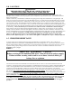
1-B. LOCATION WARNING: THE MUNCHKIN MUST BE SET ON A LEVEL SURFACE SO CONDENSATION DOES NOT BACK UP INSIDE BOILER! The Munchkin is designed for Installation on combustible flooring, in alcoves, basements, closets, utility rooms. The Munchkin shall be installed so that the gas ignition system components are protected from water. This includes all related piping and components. Choose a location for your Munchkin, centralized to the piping system, along with consideration to vent pipe length.
PART 3 3-A. GAS CONNECTION The gas supply shall have a maximum inlet pressure of less than 14" water column (350 mm), ‰ pound pressure (3.4 kPa), and a minimum of 7" water column. The entire piping system, gas meter, and regulator must be sized properly to prevent pressure drop greater than 0.5" as stated in the National Fuel Gas Code. This information is listed on the rating plate. It is very important that you are connected to the type of gas as noted on the rating plate.
It is recommended that a soapy solution be used to detect leaks. Bubbles will appear on pipe to indicate a leak is present. The gas piping must be sized for the proper flow and length of pipe, to avoid pressure drop. Both the gas meter and the gas regulator must be properly sized for the total gas load. If you experience a pressure drop greater than 1" WC, the meter or regulator or gas line is undersized or in need of service.
12) All venting must be properly supported, as the Munchkin is not intended to support any venting whatsoever. All piping, glue, solvents, cleaners, fittings and components, must conform to ASTM (American Society for Testing and Materials), and ANSI ( American National Standard Institute). It is recommended that you use one of the optional vent kits specifically for Munchkin installations.(KGAVT0601CVT (3 in.) or V1000).
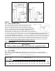
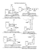
VENTING EXAMPLES TOTAL EQUIVALENT GRAND TOTAL COMBINED FRICTION TOTAL VENT LENGTH VENT LENGTH LOSS FRICTION (FEET) (FEET) QTY.
VENTING DIAGRAMS 4-F.
PART 5 5-A. HYDRONIC HEAT PIPING The Munchkin is designed to function in a closed loop 15 PSI System. To assure that there is adequate pressure in the system, we have installed in the Outlet Manifold, a pressure switch which will not let the Munchkin operate without a minimum of 10 PSI water pressure. This assures that the system does not have a leak, which could cause damage to the Munchkin System.
NOTE: For installation that incorporates Standing Iron Radiation and systems manual vents high points. Follow the Section 5-B procedure, then starting with the nearest manual air vent, open vent until water flows out, then close vent. Repeat procedure, working your way toward furthest air vent. It may be necessary to install basket strainer in an older hydronic system where larger amounts of sediment may be present. Annual cleaning of the strainer may be necessary.
4. Place in operation the appliance being inspected. Follow the lighting instructions. Adjust thermostat so appliance will operate continuously. 5. Test for spillage at the draft hood relief opening after 5 minutes of main burner operation. Use the flame of a match or candle, or smoke from a cigarette, cigar or pipe.
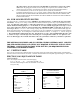
6-C. LIGHTING INSTRUCTIONS FOR YOUR SAFETY READ BEFORE OPERATING WARNING!! If you do not follow these instructions exactly , a fire or explosion may result, causing property damage, personal injury or loss of life. A. B. C. D. This appliance does not have pilot. It is equipped with an ignition device which automatically lights the burner. Do not try to light the burner by hand. BEFORE OPERATING smell all around the appliance area for gas.
PART 7 SERVICING 7-A. SEQUENCE OF OPERATION 1. When power is first applied to the control, the control will initially run through a self-diagnostic routine and then go into its operating mode. If there is no call for heat, the System will go into the idle state. 2. If the thermostat is calling for heat, the control will apply power to the circulator pump.
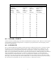
7-C MUNCHKIN BOILER FAULT LED CODE: When a fault condition occurs or is sensed on theWHC1100 Munchkin Controller or in the appliance, the control board goes to aLOCKOUTstate. When in the LOCKOUTstate, the green LED located on theWHC1100 Control board will flash a fault code. The number of times to LED flashes ON/OFF will determine the nature of the fault (see the table below).To reset the Control from the LOCKOUTstate, remove and re-apply 120VAC line power to the Control board.
Open Temperature Sensor On Inlet (Probe Fault) — 5 PULSES ! The control will sense an open temperature probe. If an open probe is sensed, the control will go into the lockout state. Verify that the Inlet probe is properly connected to the control board. If the temperature probe is in an environment of less then°F 0 then wait for ambient temperature to rise or apply heat to the unit.
MUNCHKIN CONTROLLER PART 8 8-A. MAINTENANCE PROCEDURES Periodic maintenance should be performed once a year by a qualified service technician to assure that all the equipment is in safe efficient operation. The owner can make necessary arrangements with a qualified heating contractor for periodic maintenance of the boiler. Installer must also inform owner that the lack of proper care and maintenance of the boiler may result in a hazardous condition.
LP-61r Rev 5/01/02