
Manual


20
LP- 325 REV. 3.21.14
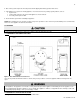
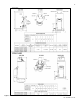
G. HYDRONIC PIPING - CIRCULATORS, ZONE VALVES AND MULTIPLE
APPLIANCES
This appliance is designed to function in a closed loop 15 PSI System. A factory
installed low water cut off will ensure that you have adequate water in the system. We
have also included a T&P gauge which allows the user to monitor system pressure
and outlet temperature from the appliance.
Install the appliance so the gas ignition system components are protected from water
(dripping, spraying, etc.) allowing clearance for basic service of circulator
replacement, valves and other parts. Observe minimum 1” clearance around all hot
water pipes not protected by non-combustible materials.
On an appliance installed above radiation level, some states and local codes require a
low water cut off device at the time of installation. If the appliance supplies hot water
to heating coils in air handler units, flow control valves or other devices must be
installed to prevent gravity circulation of appliance water in the coils during the cooling cycle. Chilled water medium must be piped in
parallel with the appliance.
Basic steps are listed below which will guide you through the installation of the appliance.
1. Connect the system return marked “Return”.
2. Connect the system supply marked “Supply”.
3. Install purge and balance valve or shut off valve and drain on system return to purge air out of each zone.
4. Install a back flow preventer on the cold feed make-up water line.
5. Install a pressure reducing valve on the cold feed make-up water line, (15 PSI nominal on the system return). Check temperature and
pressure gauge which should read minimum pressure of 12 PSI.
6. Install a circulator as shown in piping details (this section). Make sure the circulator is properly sized for the system and friction loss.
7. Install an expansion tank on the system supply. Consult manufacturer instructions for specific information relating to expansion tank
installation. Size the expansion tank for the required system volume and capacity.
8. Install supply air vent to remove air when commissioning the appliance.
9. The safety relief valve is supplied with the appliance, and must be installed on the top ¾” NPT fitting marked “T&P”. Pipe the
discharge of the safety relief valve to prevent injury in the event of pressure relief. Discharge 6” above the drain. Provide piping that is
the same size as the safety relief valve outlet. Never block the outlet of safety relief valve.
H. FILL AND PURGE HEATING SYSTEM
Attach the hose to either balance or purge hose connector or drain valve and run hose to nearest drain.
Close the other side of the balance and purge valve or the shut off valve after the drain.
Open first zone balance and purge or drain valve to let water flow out the hose. If zone valves are used, open the valves one
at a time manually. (NOTE: You should check valve manufacturer instruction prior to opening valves manually, so as not to
damage any valves.)
Manually operate fill valve regulator. When water runs out of the hose, while it’s connected to the balance and purge valve or
drain you will see a steady stream of water (without bubbles). Close balance and purge valve or drain to stop the water from
flowing. Disconnect the hose and connect it to next zone to be purged.
Repeat this procedure for additional zones (one at a time).
Table 2
APPROXIMATE TIME / TEMPERATURE RELATIONSHIPS IN SCALDS
120
o
F
More than 5 minutes
125
o
F
1 ½ to 2 minutes
130
o
F
About 30 seconds
135
o
F
About 10 seconds
140
o
F
Less than 5 seconds
145
o
F
Less than 3 seconds
150
o
F
About 1 ½ seconds
155
o
F
About 1 second