
Manual

49
LP- 325 REV. 3.21.14
3. If the thermostat is equipped with an anticipator and it is connected directly to the appliance, the anticipator should be set at .1 amps.
If the thermostat is connected to other devices, the anticipator should be set to match the power requirements of those devices. See the
instruction manual of connected devices for further information.
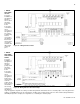
E. OUTDOOR SENSOR (OPTIONAL)
1. If an HTP 7250P-319 outdoor sensor is not used in this installation, move on to Section F.
2. Use a minimum 22 AWG wire for runs of 100 feet or less and minimum 18 AWG wire for runs of up to 150 feet.
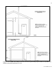
3. Mount the outdoor sensor on an exterior surface of the building, preferably on the north side in an area that will not be affected by
direct sunlight and will be exposed to varying weather conditions.
NOTE: Follow instructions provided with the sensor for detailed mounting instructions.
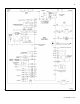
4. When correctly mounted, connect sensor to terminals marked 12 and 13.
F. INDIRECT SENSOR (OPTIONAL)
1. If an indirect water tank is not used in the installation, move on to Section G.
2. The appliance will operate an indirect fired water tank with either a thermostat type aquastat installed in the indirect tank or an HTP
7250P-325 tank sensor. When a tank sensor is used, the appliance control will automatically detect its presence and a demand for heat
from the indirect water tank will be generated when the tank temperature falls below the user set point by more than the user selectable
offset. Demand will continue until the sensor measures that the indirect water tank temperature is above the set point.
Connect the indirect tank sensor (7250P-325) or mechanical aquastat to the terminals marked 10 and 11 on the field connection board.
To control the temperature of low temperature heating circuits when using an indirect fired water heater, a thermostatic mixing valve is
required. Failure to install a thermostatic mixing valve when using an indirect fired water heater could result in damage the heating
circuits. Such damage IS NOT covered by warranty.
G. 0-10 VOLT BUILDING CONTROL SIGNAL (OPTIONAL)
1. If a 0-10 volt building management system is not used in the installation, move on to Section H.
2. A signal from a building management system may be connected to the appliance to enable remote control. This signal should be a 0-
10 volt positive-going DC signal.
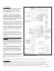
3. When this input is enabled using the installer menu, a building control system can be used to control either the set point temperature
or the heat output of the appliance. The control interprets the 0-10 volt signal as follows; when the signal is between 0 and 1.5 volts, the
appliance will be in standby mode, not firing. When the signal rises above 1.5 volts, a demand for heat is started. As the signal
continues to rise towards its maximum of 10 volts, the appliance will increase either its set point temperature or firing rate depending on
the setting of function 17 in the installer menu. See Part 10 for details on the setting of functions 16 and 17 for this option.
4. Connect a building management system or other auxiliary control signal to the terminals marked 16 (0-10 VOLT +) and 17 (0-10
VOLT –) in the electrical junction box caution should be used to ensure that the 16 (0-10 VOLT +) connection does not become
connected to ground.
H. UL353 LOW WATER CUT-OFF INTERFACE KIT (OPTIONAL)
1. If an HTP 7450P-255 UL353 Low Water Cut-Off (LWCO) Kit is not used, move on to Section I.
2. The control box of the kit should be mounted to the left side of the appliance near the low water cut-off probe, which is located near
the outlet nipple of the appliance.
3. Follow the complete instructions included in the kit for proper installation.
I. WIRING OF APPLIANCE ALARM (OPTIONAL)
An alarm bell or light can be connected to the alarm connection of the appliance. In the event of an alarm, the alarm connection may be
used to power a 120V device. The alarm connections are rated 3 amps at 120 VAC. Connect to terminal 1 (HOT), 2 (NEUT), and 3
(GND).
J. VERSA-FLAME WIRING FOR DHW PRIORITY WITH ZONE VALVES OR CIRCULATORS
For proper installation of the appliance with zone relay panels, follow the wiring instructions in Subsections 1 and 2 below. It is critical
that the installation is followed for proper DHW Priority.