
Manual

60
LP- 325 REV. 3.21.14
5. Press {S3} a fifth time to access the final adjustment in this mode – |t|, the Temperature Measurement in Fahrenheit to Celsius. To
change value, press either {S1} or {S2} to change the measurement from F (Fahrenheit) to C (Celsius).
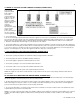
D. STATUS MENU
Installers are also able to check the current status of the appliance parameters by pressing {S4} for 3 seconds. Once activated, the
display will show |d1| alternating value of the actual outlet temperature. Actual values are displayed for each function. To view the next
value, simply press the {S4} key.
Listed below are the values which can be displayed. These values cannot be changed. To exit this menu, simply press {S3} to resume
normal operation.
Function – Value
To toggle between values press {S1} to go down and {S4} to go up. The first function you will see is:
|d1| — Actual temperature from top sensor
|d2| — Actual temperature from bottom sensor
|d3| — PIONEER: Actual tank temperature if an indirect sensor is used.
*VERSA-FLAME: Displays the state of DHW demand – 1 if flow switch is active (closed)
0 if flow switch is not active (open)
|d4| — Not used
|d5| — Actual temperature from the outdoor sensor |NC|.
|d6| — Actual fan speed multiplied by 10 (Example: If fan speed displayed is |410| RPM x 10 = 4100 actual fan speed)
|d7| — Actual ionization current read from flame rectification probe
|d8| — Actual status of the central heating circulator Off = |0|, On = |1|.
|d9| — Actual status of the indirect fired circulator Off = |0|, On = |1|.
*VERSA-FLAME: Status of the DHW module pump Off = |0|, On = |1|.
|d10| — Actual status of bus communication |co| = connected, |nc| = not connected
|d11| — Central heating set point
|d12| — Power on hours in thousands (display will not read until 100 hrs.)
|d13| — Total central heat hours in thousands (display will not read until 100 hrs.)
|d14| — Total indirect/dhw hours in thousands (display will not read until 100 hrs.)
|d15| — Passed ignition attempts in thousands
|d16| — This function only becomes active when appliance is set as the Master. It allows the user to monitor the System Pump
connected to the Master Appliance (0 = Off, 1 = On) in a multiple appliance installation. Each appliance firing output percent is
displayed.
|P0| - Master Appliance - Alternating (0-100 Percentage firing rate)
|P1| - Follower Appliance #1 – Alternating (0-100 Percentage firing rate)
|P2| - Follower Appliance #2 – Alternating (0-100 Percentage firing rate)
|P3| - Follower Appliance #3 – Alternating (0-100 Percentage firing rate)
|P4| - Follower Appliance #4 – Alternating (0-100 Percentage firing rate)
|P5| - Follower Appliance #5 – Alternating (0-100 Percentage firing rate)
|P6| - Follower Appliance #6 – Alternating (0-100 Percentage firing rate)
|P7| - Follower Appliance #7 – Alternating (0-100 Percentage firing rate