AAU3940 Installation Guide Issue 01 Date 2015-01-15 HUAWEI TECHNOLOGIES CO., LTD.
Copyright © Huawei Technologies Co., Ltd. 2015. All rights reserved. No part of this document may be reproduced or transmitted in any form or by any means without prior written consent of Huawei Technologies Co., Ltd. Trademarks and Permissions and other Huawei trademarks are trademarks of Huawei Technologies Co., Ltd. All other trademarks and trade names mentioned in this document are the property of their respective holders.
AAU3940 Installation Guide About This Document About This Document Overview This document describes procedures for installing an active antenna unit 3940 (AAU3940, which is shortened to AAU in this document) and its cables. It also provides the checklists for hardware installation. Product Version The following table lists the product versions related to this document. Product Name Solution Version Product Version DBS3900 l SRAN9.0 and later V100R009C00 and later l RAN16.0 and later l eRAN7.
AAU3940 Installation Guide About This Document This chapter lists the tools and instruments that must be obtained before the installation. It also specifies the skills that the onsite personnel must have. 4 Unpacking Check Unpack and check the delivered equipment to ensure that all materials are included and intact. 5 Installation Process This chapter describes the process of installing an AAU. 6 (Optional) Installing an ODM This section describes the procedure and precautions for installing an ODM.
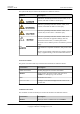
AAU3940 Installation Guide About This Document The symbols that may be found in this document are defined as follows. Symbol Description Indicates an imminently hazardous situation which, if not avoided, will result in death or serious injury. Indicates a potentially hazardous situation which, if not avoided, could result in death or serious injury. Indicates a potentially hazardous situation which, if not avoided, may result in minor or moderate injury.
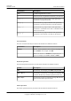
AAU3940 Installation Guide About This Document Convention Description Italic Command arguments are in italics. [] Items (keywords or arguments) in brackets [ ] are optional. { x | y | ... } Optional items are grouped in braces and separated by vertical bars. One item is selected. [ x | y | ... ] Optional items are grouped in brackets and separated by vertical bars. One item is selected or no item is selected. { x | y | ... }* Optional items are grouped in braces and separated by vertical bars.
AAU3940 Installation Guide Issue 01 (2015-01-15) About This Document Action Description Click Select and release the primary mouse button without moving the pointer. Double-click Press the primary mouse button twice continuously and quickly without moving the pointer. Drag Press and hold the primary mouse button and move the pointer to a certain position. Huawei Proprietary and Confidential Copyright © Huawei Technologies Co., Ltd.
AAU3940 Installation Guide Contents Contents About This Document.....................................................................................................................ii 1 Changes in AAU3940 Installation Guide..................................................................................1 2 Overview.........................................................................................................................................2 2.1 Installation Scenario.............................
AAU3940 Installation Guide Contents 11 Closing a Maintenance Cavity................................................................................................86 12 (Optional) Installing a Cord Cover for an ODM.................................................................87 13 Adjusting the Horizontal Azimuth of an Antenna.............................................................89 14 Installation Checklist..........................................................................................
AAU3940 Installation Guide 1 1 Changes in AAU3940 Installation Guide Changes in AAU3940 Installation Guide This section describes changes in AAU3940 Installation Guide. 01 (2015-01-15) This is the first commercial release. Compared with issue Draft A (2014-10-30), no information is added to or deleted from this issue. Compared with issue Draft A (2014-10-30), this issue includes the following changes.
AAU3940 Installation Guide 2 Overview 2 Overview About This Chapter Before installing an AAU, you must be familiar with its installation options and installation clearance requirements. 2.1 Installation Scenario An AAU can be installed independently or can be installed together with an ODM04A (ODM for short) on a pole, a wall, or the top of a pole. 2.2 Installation Clearance Requirements This section describes installation clearance requirements in different scenarios. 2.
AAU3940 Installation Guide 2 Overview 2.1 Installation Scenario An AAU can be installed independently or can be installed together with an ODM04A (ODM for short) on a pole, a wall, or the top of a pole. Installation Scenario Description NOTE An AAU has been camouflaged and the second camouflaging is not allowed in principle. If the second camouflaging must be performed, you need to contact Huawei technical engineers for assessment.
AAU3940 Installation Guide 2 Overview Figure 2-1 Scenario in which AAUs are installed independently a: Scenario in which three AAUs are b: Scenario in which two AAUs are c: Scenario in which one AAU is installed on a pole installed on a pole installed on a pole d: Scenario in which an AAU is installed on a wall Issue 01 (2015-01-15) e: Scenario in which an AAU is installed on the top of a pole Huawei Proprietary and Confidential Copyright © Huawei Technologies Co., Ltd.
AAU3940 Installation Guide 2 Overview The following figure shows scenarios in which AAUs are installed together with ODMs. NOTE AAUs can also be installed together with optical distribution frames (ODFs). This document uses ODMs as examples. Issue 01 (2015-01-15) Huawei Proprietary and Confidential Copyright © Huawei Technologies Co., Ltd.
AAU3940 Installation Guide 2 Overview Figure 2-2 Scenarios in which AAUs are installed together with ODMs a: Scenario in which three AAUs are b: Scenario in which two AAUs are c: Scenario in which an AAU is installed together with an ODM on a installed together with an ODM on a installed together with an ODM on a pole pole pole Issue 01 (2015-01-15) Huawei Proprietary and Confidential Copyright © Huawei Technologies Co., Ltd.
AAU3940 Installation Guide 2 Overview d: Scenario in which an AAU is e: Scenario in which an AAU is installed together with an ODM on a installed on the top of a pole and an wall ODM is installed on a wall NOTICE In all scenarios, AAUs are installed together with their bottoms facing downwards. The vertical deviation angle of a support must be less than or equal to 5 degrees, as shown in the following figure.
AAU3940 Installation Guide 2 Overview Table 2-1 Requirements of installation scenarios Installation Scenario Requirements One AAU is installed on a pole. l The part of a pole for installing an AAU should have a diameter of 60 mm to 300 mm (2.36 in. to 11.81 in.) and the recommended wall thickness of a pole is greater than or equal to 4 mm (0.16 in.). l If the part of a pole for installing an AAU has a diameter greater than 300 mm (11.81 in.), an auxiliary pole is required for installing the AAU.
AAU3940 Installation Guide 2 Overview The method of connecting a flange plate to the top of a pole is determined by customers. The following figure shows the design specifications of ports on a flange plate for connecting an AAU. Figure 2-4 Design specifications of ports on a flange plate (1) Flange plate (2) Screw hole (3) Nut 2.2 Installation Clearance Requirements This section describes installation clearance requirements in different scenarios.
AAU3940 Installation Guide 2 Overview Figure 2-5 AAU installation clearance requirements The following figure shows the clearance requirements for installing an ODM. Issue 01 (2015-01-15) Huawei Proprietary and Confidential Copyright © Huawei Technologies Co., Ltd.
AAU3940 Installation Guide 2 Overview Figure 2-6 ODM installation clearance requirements 2.3 AAU Mounting Kits This section describes mounting kits for installing AAUs on a pole, a wall, and the top of a pole. Mounting Kits for an AAU Installed on a Pole or Wall The same mounting kits are used for installing an AAU on a pole and installing an AAU on a wall. However, the procedure for installing an AAU on a pole is different from that for installing an AAU on a wall.
AAU3940 Installation Guide 2 Overview Figure 2-7 Mounting kits for an AAU installed on a pole or wall (1) Attachment plate (2) M8x80 expansion anchor bolt (3) Main mounting bracket (4) Steel belt Mounting Kits for an AAU Installed on the Top of a Pole Mounting kits for installing an AAU on the top of a pole include a support and a landscaping cover, as shown in the following figure.
AAU3940 Installation Guide 2 Overview Function The ODM is an auxiliary low-power AC device for providing power distribution and fiber distribution. The ODM cover provides fiber distribution and the ODM provides power distribution. The following figure shows the structure of an ODM.
AAU3940 Installation Guide 2 Overview Table 2-2 ODM specifications Item Specifications Dimensions (H x W x D) 232 mm x 158 mm x 96.5 mm (9.13 in. x 6.22 in. x 3.80 in.) Upper-level circuit breaker 20 A Support power 1650 W Power supply capacity One AC power input and four AC power outputs (Each power output is less than or equal to 400 W.
AAU3940 Installation Guide 2 Overview Figure 2-10 Mounting kits for an ODM (1) Attachment plate (2) Mounting bracket (3) Steel belt (4) Expansion bolt 2.5 Surge Protection Requirements When an AAU is installed on a pole or the top of a pole, the AAU must meet the surge protection requirements. Otherwise, surge protection measures must be taken.
AAU3940 Installation Guide 2 Overview The following figure shows AAU installation scenarios in which surge protection measures are taken. Figure 2-11 AAU installation scenarios in which surge protection measures are taken (1) Lightning rods (2) AAUs (3) AAU PGND cables (4) Ground bars of ground girds (5) PGND cables for metal poles - Issue 01 (2015-01-15) Huawei Proprietary and Confidential Copyright © Huawei Technologies Co., Ltd.
AAU3940 Installation Guide 3 Installation Preparations 3 Installation Preparations About This Chapter This chapter lists the tools and instruments that must be obtained before the installation. It also specifies the skills that the onsite personnel must have. 3.1 Documents This section lists the documents that must be obtained before the installation. 3.2 Tools and Instruments You must prepare the following tools and instruments before the installation. 3.
AAU3940 Installation Guide 3 Installation Preparations 3.1 Documents This section lists the documents that must be obtained before the installation. l Before the installation, familiarize yourself with related information in the following documents: – AAU3940 Hardware Description – Safety Information l During the installation, refer to the following document: – Installation Reference 3.2 Tools and Instruments You must prepare the following tools and instruments before the installation.
AAU3940 Installation Guide 3 Installation Preparations Level Torque screwdriver Torque socket Multimeter Marker (diameter ≤ 10 mm or 0.39 in.) Measuring tape Hex key Fixed pulley Lifting sling Hydraulic pliers Fiber fusion splicer Geologic compass Hammer drill 3.3 Requirements for Onsite Personnel Onsite personnel must be qualified and trained. Before performing any operation, onsite personnel must be familiar with correct operation methods and safety precautions.
AAU3940 Installation Guide 3 Installation Preparations l Issue 01 (2015-01-15) The number of onsite personnel depends on the engineering schedule and installation environment. Generally, four to five onsite personnel are necessary. Huawei Proprietary and Confidential Copyright © Huawei Technologies Co., Ltd.
AAU3940 Installation Guide 4 Unpacking Check 4 Unpacking Check Unpack and check the delivered equipment to ensure that all materials are included and intact. Context NOTE When transporting, moving, or installing equipment or components, l Prevent them from colliding with doors, walls, shelves, or other objects. l Avoid touching their unpainted metal surfaces with sweat-soaked or dirty gloves or bare hands. NOTICE Power on an AAU within 24 hours after unpacking it.
AAU3940 Installation Guide 4 Unpacking Check If... Then... The outer packing is severely damaged or Find out the cause and report the situation to soaked the local Huawei office. Step 3 Check the type and quantity of the equipment in the cases according to the packing list. If... Then... Types and quantity of the articles tally with Sign the Packing List with the customer.
AAU3940 Installation Guide 5 Installation Process 5 Installation Process This chapter describes the process of installing an AAU. The following figure shows the installation process. Issue 01 (2015-01-15) Huawei Proprietary and Confidential Copyright © Huawei Technologies Co., Ltd.
AAU3940 Installation Guide 5 Installation Process Figure 5-1 Installation process Issue 01 (2015-01-15) Huawei Proprietary and Confidential Copyright © Huawei Technologies Co., Ltd.
AAU3940 Installation Guide 6 (Optional) Installing an ODM 6 (Optional) Installing an ODM This section describes the procedure and precautions for installing an ODM. Context The part of a pole for installing the mounting bracket of an ODM should have a diameter of 114 mm to 380 mm (4.489 in. to 14.96 in.). Procedure l Installing an ODM on a wall 1.
AAU3940 Installation Guide 6 (Optional) Installing an ODM 2. Drill holes at the anchor points and install expansion bolts in the holes, as shown in the following figure. a. Use a hammer drill with a Φ8 bit to drill holes vertically at the marked anchor points. Ensure that the depth of each hole ranges from 50 mm to 60 mm (1.97 in. to 2.36 in.). b. Use a vacuum cleaner to clear the dust inside and around the holes, and measure the distances between holes.
AAU3940 Installation Guide 6 (Optional) Installing an ODM Figure 6-3 Tightening a mounting bracket to the installation position on a wall (1) Nut (2) Spring washer (3) Flat washer 4. Fit the two dowels on the top of the ODM backplane into the mounting bracket, and push the ODM case until it is attached onto the mounting bracket, as shown by illustrations a and b in the following figure. 5.
AAU3940 Installation Guide 6 (Optional) Installing an ODM l Installing an ODM on a pole 1. Determine a position for installing an ODM on a pole, attach a mounting bracket to the installation position on the pole, put the steel belts through the mounting bracket, and wind the steel belts round the pole for one circle, as shown by illustrations a, b, and c in the following figure. 2.
AAU3940 Installation Guide 6 (Optional) Installing an ODM Figure 6-6 Installing an ODM to a mounting bracket ----End Issue 01 (2015-01-15) Huawei Proprietary and Confidential Copyright © Huawei Technologies Co., Ltd.
AAU3940 Installation Guide 7 7 Preprocessing the AAU Maintenance Cavity Preprocessing the AAU Maintenance Cavity Before installing an AAU, take power terminals out of its maintenance cavity and install optical modules. Procedure Step 1 Use an M6 inner hexagon torque screwdriver to loosen the screw on the maintenance cavity and open the maintenance cavity. Then take out of power terminals, as shown in the following figure.
AAU3940 Installation Guide 7 Preprocessing the AAU Maintenance Cavity Figure 7-2 Installing the optical module NOTICE The performance of an optical module may deteriorate if it is exposed to the air for more than 20 minutes. Therefore, insert a fiber optic cable into an unpacked optical module within 20 minutes. Step 4 Use an M6 inner hexagon torque screwdriver to tighten the screw on the maintenance cavity to 7 N·m (61.95 lbf·in.), as shown in the following figure.
AAU3940 Installation Guide 7 Preprocessing the AAU Maintenance Cavity Figure 7-3 Closing a maintenance cavity Step 5 Install the attachment plate on the maintenance cavity of the AAU to be installed, and use an M6 inner hexagon torque screwdriver to tighten the screws to 7 N·m (61.95 lbf·in.), as shown in the following figure. Issue 01 (2015-01-15) Huawei Proprietary and Confidential Copyright © Huawei Technologies Co., Ltd.
AAU3940 Installation Guide 7 Preprocessing the AAU Maintenance Cavity Figure 7-4 Installing an attachment plate ----End Issue 01 (2015-01-15) Huawei Proprietary and Confidential Copyright © Huawei Technologies Co., Ltd.
AAU3940 Installation Guide 8 Lifting an AAU 8 Lifting an AAU Before installing an AAU on a pole, you need to lift the AAU to the installation position on the pole. Prerequisites You have preprocessed the AAU maintenance cavity. For detailed operations, see 7 Preprocessing the AAU Maintenance Cavity. Context It is recommended that a tail-lift truck be used to lift installation personnel and equipment to the installation position. If there is no tail-lift truck, a reliable and safe scaffold can be used.
AAU3940 Installation Guide 8 Lifting an AAU Figure 8-1 Lifting mounting kits Step 2 Use the lifting sling to bind the handle on the top of the AAU and use the traction sling to bind the lower part of the AAU, as shown in the following figure.
AAU3940 Installation Guide 8 Lifting an AAU Figure 8-3 Lifting an AAU ----End Issue 01 (2015-01-15) Huawei Proprietary and Confidential Copyright © Huawei Technologies Co., Ltd.
AAU3940 Installation Guide 9 Installing an AAU 9 Installing an AAU About This Chapter This chapter describes the procedures for installing an AAU in different scenarios. 9.1 Installing an AAU on a Pole This section describes the procedure and precautions for installing an AAU on a pole. 9.2 Installing an AAU on the Top of a Pole This section describes the procedure and precautions for installing an AAU on the top of a pole. 9.
AAU3940 Installation Guide 9 Installing an AAU 9.1 Installing an AAU on a Pole This section describes the procedure and precautions for installing an AAU on a pole. Prerequisites l You have preprocessed the AAU maintenance cavity. For detailed operations, see 7 Preprocessing the AAU Maintenance Cavity. l You have lifted the AAU and mounting kits to the installation position on the pole. For detailed operations, see 8 Lifting an AAU.
AAU3940 Installation Guide 9 Installing an AAU Figure 9-1 Putting the steel belt through the sliding block Step 3 Pull the steel belts to align the holes on the steel belts with those on the sliding blocks, as shown in the following figure. NOTE If the pin on a sliding block is located between two holes on a steel belt after the belt is securely attached to the pole, slightly loosen the steel belt so that the pin goes through a hole on the steel belt.
AAU3940 Installation Guide 9 Installing an AAU Figure 9-2 Installing the main mounting bracket Step 4 Use an M10 inner hexagon wrench to tighten the bolts on the two steel belts alternately to secure the main mounting bracket to 28 N·m (247.8 lbf·in.), as shown in the following figure. NOTE Tighten the bolts clockwise to slide a sliding block on a steel belt towards bolt heads and securely attach the steel belt.
AAU3940 Installation Guide 9 Installing an AAU Figure 9-3 Securing a main mounting bracket Step 5 Use a cable cutter to cut off the excess of steel belts and reserve a slack of 20 mm to 30 mm (0.79 in. to 1.18 in.), and wrap insulation tape around the ends of the belts to prevent personal injury, as shown in the following figure.
AAU3940 Installation Guide 9 Installing an AAU Step 6 Attach the AAU to the main mounting bracket, and use an M6 inner hexagon screwdriver to tighten the screw on the main mounting bracket to 7 N·m (61.95 lbf·in.), as shown in the following figure. Figure 9-5 Installing an AAU on a main mounting bracket Step 7 Optional: Install the second AAU. NOTICE Before installing the second AAU, ensure that the mounting kits for the first AAU have been securely installed. 1.
AAU3940 Installation Guide 9 Installing an AAU 3. Install the AAU to the mounting kits according to Step 6. Step 8 Optional: Install the third AAU. NOTICE Before installing the third AAU, ensure that the mounting kits for the first and second AAUs have been securely installed. 1. Put the steel belts of the mounting kits for the third AAU through the evading holes of the mounting kits for the first and second AAUs, as shown in the following figure. 2.
AAU3940 Installation Guide 9 Installing an AAU Figure 9-7 Three AAUs installed on a pole (1) Lightning rod ----End 9.2 Installing an AAU on the Top of a Pole This section describes the procedure and precautions for installing an AAU on the top of a pole. Prerequisites l Issue 01 (2015-01-15) You have preprocessed the AAU maintenance cavity. For detailed operations, see 7 Preprocessing the AAU Maintenance Cavity. Huawei Proprietary and Confidential Copyright © Huawei Technologies Co., Ltd.
AAU3940 Installation Guide 9 Installing an AAU Context NOTICE Do not work at heights when you meet any of the following situations: l Thunder, lightning, rain, or wind greater than force 6 occurs. l Water remains on the surface of the steel tube. l There may be other danger. After the above situations are eliminated, the Huawei security director and related technical personnel must check all devices to be used before work start. Procedure Step 1 Lift the landscaping cover and remove it.
AAU3940 Installation Guide 9 Installing an AAU Figure 9-8 Securing a mounting bracket Step 3 Put the AAU on the mounting bracket on the top of a pole with both hands, and tighten four M6 inner hexagon bolts to secure the AAU, a shown in the following figure. Issue 01 (2015-01-15) Huawei Proprietary and Confidential Copyright © Huawei Technologies Co., Ltd.
AAU3940 Installation Guide 9 Installing an AAU Figure 9-9 Installing an AAU Step 4 Install the removed landscaping cover. NOTE It is recommended that the landscaping cover be installed after cables are connected. 1. Put the landscaping cover on the AAU, and press the elastomer on the mounting bracket when the landscaping cover reaches the top of the mounting bracket so that it can slide down. 2.
AAU3940 Installation Guide 9 Installing an AAU Figure 9-10 Installing a landscaping cover (1) Elastomer (2) Trough (3) Support brace ----End 9.3 Installing an AAU on a Wall This section describes the procedure and precautions for installing an AAU on a wall. Prerequisites l Issue 01 (2015-01-15) You have preprocessed the AAU maintenance cavity. For detailed operations, see 7 Preprocessing the AAU Maintenance Cavity. Huawei Proprietary and Confidential Copyright © Huawei Technologies Co., Ltd.
AAU3940 Installation Guide 9 Installing an AAU Procedure Step 1 Remove the steel belts from mounting kits, as shown in the following figure. 1. Use a Phillips screwdriver to remove four screws from the cover plate. 2. Use an M6 inner hexagon wrench to remove the bolts from the steel belts. 3. Remove the steel belts from the mounting kits. Issue 01 (2015-01-15) Huawei Proprietary and Confidential Copyright © Huawei Technologies Co., Ltd.
AAU3940 Installation Guide 9 Installing an AAU Figure 9-11 Removing steel belts Step 2 Place the main bracket against the wall, use a level to verify that the main bracket is placed horizontally, and use a maker to mark anchor points, as shown in the following figure. Issue 01 (2015-01-15) Huawei Proprietary and Confidential Copyright © Huawei Technologies Co., Ltd.
AAU3940 Installation Guide 9 Installing an AAU Figure 9-12 Marking anchor points (1) Level (2) Screw hole (3) Marker Step 3 Drill holes at the anchor points, and then insert expansion anchor bolts, as shown in the following figure. 1. Use a hammer drill with a Φ10 bit to drill holes vertically at the marked anchor points. Ensure that the depth of each hole ranges from 55 mm to 60 mm (2.17 in. to 2.36 in.). 2.
AAU3940 Installation Guide 9 Installing an AAU Figure 9-13 Drilling a hole and inserting expansion anchor bolts (1) M8x80 bolt (2) Nut (3) Spring washer (4) Flat washer (5) Expansion tube NOTICE After dismantling an expansion anchor bolt, ensure that the top of the expansion tube is on the same level as the wall. Otherwise, the main mounting bracket cannot be installed on the wall evenly and securely.
AAU3940 Installation Guide 9 Installing an AAU Figure 9-14 Installing the main mounting bracket (1) Nut (2) Spring washer (3) Flat washer Step 5 Install the attachment plate on the maintenance cavity of the AAU to be installed, and use an M6 inner hexagon torque screwdriver to tighten the screws to 7 N·m (61.95 lbf·in.), as shown in the following figure. Figure 9-15 Installing an attachment plate Issue 01 (2015-01-15) Huawei Proprietary and Confidential Copyright © Huawei Technologies Co., Ltd.
AAU3940 Installation Guide 9 Installing an AAU Step 6 Attach the AAU to the main mounting bracket, and tighten the bolts on the main mounting bracket, as shown in the following figure. Figure 9-16 Installing an AAU on a main mounting bracket ----End Issue 01 (2015-01-15) Huawei Proprietary and Confidential Copyright © Huawei Technologies Co., Ltd.
AAU3940 Installation Guide 10 Installing AAU Cables 10 Installing AAU Cables About This Chapter This section describes the procedure and precautions for installing AAU cables. 10.1 Cabling Requirements Cables must be laid out according to the specified cabling requirements to prevent signal interference. 10.2 Installing an AAU PGND Cable This section describes the procedure and precautions for installing an AAU PGND cable. 10.
AAU3940 Installation Guide 10 Installing AAU Cables 10.1 Cabling Requirements Cables must be laid out according to the specified cabling requirements to prevent signal interference. NOTE If a cable listed below is not required, skip the cabling requirements of the cable. General Cabling Requirements Bending radius requirements l The bending radius of a 7/8'' feeder must be greater than 250 mm (9.84 in.), and the bending radius of a 5/4'' feeder must be greater than 380 mm (14.96 in.).
AAU3940 Installation Guide 10 Installing AAU Cables l Reserve drip loops for all cables outside the feeder window before routing them into the room. Ensure that the radiuses of the drip loops are greater than or equal to the minimum bending radiuses of the cables. l When routing a cable into the room, ensure that a person is assisting you in the room. l Apply waterproof treatment to the feeder window.
AAU3940 Installation Guide 10 Installing AAU Cables Figure 10-1 Exterior of the clips (1) Cable hole for feeders (2) Cable hole for fiber optic cables (3) Cable hole for power cables The following figure shows the cables secured on a cable tray. Figure 10-2 Cables secured on a cable tray (1) 3-hole clip (2) 6-hole clip The following figure shows the cables secured on a tower. Issue 01 (2015-01-15) Huawei Proprietary and Confidential Copyright © Huawei Technologies Co., Ltd.
AAU3940 Installation Guide 10 Installing AAU Cables Figure 10-3 Cables secured on a tower (1) 3-hole clip (2) 6-hole clip Special Cabling Requirements Cabling of power cables l Power cables must be installed in the position specified in engineering design documents. l If the length of power cables is insufficient, replace the cables rather than adding connectors or soldering joints to lengthen the cables. l Cables can only be laid out under well-planned instructions.
AAU3940 Installation Guide 10 Installing AAU Cables l After routing a DC power cable onto the platform on a tower, route it along the shortest path to the rails surrounding the platform, and route it along the inside of the rails. l After routing a DC power cable close to the equipment on a tower, use clips to secure the power cable onto a pole or the rails surrounding the platform.
AAU3940 Installation Guide 10 Installing AAU Cables l The operating temperature of fiber optic cables ranges from -40ºC to +60ºC (-40ºF to +140ºF). If the actual temperature is beyond this range, take protective measures or select another route. l Do not circle and twist cables. l Do not bind a fiber optic cable at the position where it bends. l Do not stretch, step on, or place heavy objects on fiber optic cables. Keep the fiber optic cables away from sharp objects.
AAU3940 Installation Guide 10 Installing AAU Cables Figure 10-7 CPRI fiber optic cables routed in the cabinet (2) Figure 10-8 FE/GE fiber optic cables routed in the cabinet l After routing a fiber optic cable onto the platform on a tower, route it along the shortest path to the rails surrounding the platform, and route it along the inside of the rails.
AAU3940 Installation Guide 10 Installing AAU Cables Table 10-1 Specifications of an AAU PGND cable Cable End Connecting to the AAU End Connecting to the Ground Bar Color AAU PGND cable OT terminal (M6, 16 mm2 or 0.025 in.2) OT terminal (M8, 16 mm2 or 0.025 in.2) Green and yellow Procedure Step 1 Prepare a PGND cable. 1. Cut the cables to the length suitable for the actual cable route. 2.
AAU3940 Installation Guide 10 Installing AAU Cables Figure 10-9 Installing a PGND cable when an AAU is installed on a pole Issue 01 (2015-01-15) Huawei Proprietary and Confidential Copyright © Huawei Technologies Co., Ltd.
AAU3940 Installation Guide 10 Installing AAU Cables Figure 10-10 Installing a PGND cable when an AAU is installed on a wall Issue 01 (2015-01-15) Huawei Proprietary and Confidential Copyright © Huawei Technologies Co., Ltd.
AAU3940 Installation Guide 10 Installing AAU Cables Figure 10-11 Installing a PGND cable when an AAU is installed on the top of a pole NOTE When installing a PGND cable, tightly press the OT terminal in the correct direction, as shown in the following figure. Figure 10-12 Installing an OT terminal correctly 2. Connect the other end of the PGND cable with an M8 OT terminal to the external ground bar. Step 3 Optional: When two or three AAUs are installed on a pole, equipotential cable(s) are required.
AAU3940 Installation Guide 10 Installing AAU Cables Figure 10-13 Installing equipotential cables when multiple AAUs are installed on a pole Step 4 Lay out the cables according to the instructions in Cabling Requirements, and use cable ties to bind them. Step 5 Label the installed cables according to the instructions in Attaching a Sign Plate Label. ----End 10.3 Installing an AAU Power Cable This section describes the process and precautions for installing an AAU power cable.
AAU3940 Installation Guide 10 Installing AAU Cables Table 10-2 AAU power cables Scenari o One End The Other End Connector Install ation Positi on Connector Installation Position No ODM is configur ed. Tool-less female connector (pressfit type) POWE R-IN port on an AAU Depending on the power equipment Power equipment An ODM is configur ed.
AAU3940 Installation Guide 10 Installing AAU Cables – If no ODM is configured, add the corresponding connector to the power cable according to the type of the port on the power equipment. – If an ODM is configured, add cord end terminals to the end of the power cable connected to the ODM according to the instructions in Assembling the Cord End Terminal and the Power Cable. l Connecting an AAU power cable to an AAU 1.
AAU3940 Installation Guide 10 Installing AAU Cables c. Use an M4 torque screwdriver to tighten the screws indicated by a and b in the following figure to 1.4 N·m (12.39 lbf·in.) in sequence. Figure 10-15 Securing a power cable l Connecting an AAU power cable to power equipment If... Then... No ODM is configured Connect the other end of the AAU power cable to the corresponding port on external power equipment. An ODM is configured Perform the following operations. 1.
AAU3940 Installation Guide 10 Installing AAU Cables gel in the cable holes through which no cables are routed because silica gel is required to provide the waterproof function. 2. Use insulation tape to wrap cord end terminals of the power cable to prevent sharp edges of the cord end terminal from damaging silica gel. 3. Apply petroleum jelly to the power cable, and then route the power cable through a cable hole. 4.
AAU3940 Installation Guide 10 Installing AAU Cables l Lay out the cables according to the instructions in Cabling Requirements, and use cable ties to bind them. l Label the installed cables according to the instructions in Attaching a Cable-Tying Label. ----End 10.4 Installing an ODM Power Cable This section describes the process and precautions for installing an ODM power cable when an ODM is configured. Context The following table describes the ODM power cable connections.
AAU3940 Installation Guide 10 Installing AAU Cables Step 7 Securely bind the power cable to the binding bracket, as shown in the following figure. Figure 10-17 Installing an ODM power cable Step 8 Connect the other end of the ODM power cable to the external power equipment. Step 9 Lay out the cables according to the instructions in Cabling Requirements, and use cable ties to bind them. Step 10 Label the installed cables according to the instructions in Attaching a Cable-Tying Label. ----End 10.
AAU3940 Installation Guide 10 Installing AAU Cables Figure 10-18 Installing CPRI fiber optic cables (1) CPRI fiber optic cable between (2) CPRI fiber optic cable between (3) CPRI fiber optic cable between an AAU and a BBU an AAU and an ODM an ODM and a BBU NOTE l The single-mode optical module is labeled as SM and the multimode optical module is labeled as MM. l The puller of a single-mode optical module is blue and the puller of a multimode optical module is black or gray.
AAU3940 Installation Guide 10 Installing AAU Cables Procedure l Stripping a trunk fiber optic cable and pigtails 1. Use a screwdriver to pierce silica gel in the cable hole on the ODM for the trunk fiber optic cable, as shown by illustration a in the following figure. 2. Route a trunk fiber optic cable through the cable hole, as shown by illustration b in the following figure. Figure 10-20 Routing a trunk fiber optic cable through a cable hole (1) Screwdriver 3.
AAU3940 Installation Guide 10 Installing AAU Cables Figure 10-21 Stripping a specified length of sheath off a trunk fiber optic cable (1) Strength member 4. (2) Core wire (3) Bare fiber Strip a specified length of sheath off the pigtail, as shown in the following figure. Figure 10-22 Stripping a specified length of sheath off a pigtail (1) Sheath l Issue 01 (2015-01-15) (2) Core wire (3) Bare fiber Installing a trunk fiber optic cable 1.
AAU3940 Installation Guide 10 Installing AAU Cables Figure 10-23 Installing a trunk fiber optic cable l Installing a pigtail 1. Attach labels delivered with the splicing tray in the ODM to both ends of the pigtails to be installed. NOTE The following figure shows the first group of labeled pigtails. Figure 10-24 First group of labeled pigtails Issue 01 (2015-01-15) Huawei Proprietary and Confidential Copyright © Huawei Technologies Co., Ltd.
AAU3940 Installation Guide 10 Installing AAU Cables 2. Insert the end of the pigtails with FC connectors to the adapter delivered with the ODM, coil the fiber optic cable clockwise, and route the fiber optic cable through the cable hole in the splicing tray, as shown in the following figure. NOTE This section uses FC connectors as examples. SC or LC connectors can be added to pigtails.
AAU3940 Installation Guide 10 Installing AAU Cables Figure 10-26 Coiling the spliced fiber optic cable (1) Trunk fiber optic cable (2) Heat shrink tubing (3) Pigtail NOTICE To open the ODM case for maintenance, a minimum of 40 mm (1.57 in.) fiber optic cable is reserved outside the ODM case, as shown in the following figure. Issue 01 (2015-01-15) Huawei Proprietary and Confidential Copyright © Huawei Technologies Co., Ltd.
AAU3940 Installation Guide 10 Installing AAU Cables Figure 10-27 Reserving slack of a CPRI fiber optic cable a: Scenario in which a pole is used b: Scenario in which a pole is used c: Scenario in which a wall is used (routing a cable along the inner (routing a cable along the outer side of the pole) side of the pole) l Lay out the cables according to the instructions in Cabling Requirements, and use cable ties to bind them.
AAU3940 Installation Guide 10 Installing AAU Cables Figure 10-28 Installing CPRI fiber optic cables (1) CPRI fiber optic cable between (2) CPRI fiber optic cable between (3) CPRI fiber optic cable between an AAU and a BBU an AAU and an ODM an ODM and a BBU NOTICE The optical modules to be installed must match the rates of their corresponding CPRI ports. NOTE l The single-mode optical module is labeled as SM and the multimode optical module is labeled as MM.
AAU3940 Installation Guide 10 Installing AAU Cables NOTICE The performance of an optical module may deteriorate if it is exposed to the air for more than 20 minutes. Therefore, insert a fiber optic cable into an unpacked optical module within 20 minutes. Procedure l Connecting a CPRI fiber optic cable to an AAU 1. Route a CPRI fiber optic cable into the maintenance cavity through the rear of the maintenance cavity. 2.
AAU3940 Installation Guide 10 Installing AAU Cables Figure 10-31 Connecting a CPRI fiber optic cable to an AAU (b) (1) Fiber concentrator l Installing a CPRI fiber optic cable between a BBU and an ODM If... Then... The CPRI fiber optic cable is to be Insert the other end of the fiber optic cable into the connected the BBU optical module on the BBU side. The CPRI fiber optic cable is to be Perform the following operations. connected to the ODM Issue 01 (2015-01-15) 1.
AAU3940 Installation Guide 10 Installing AAU Cables the corresponding port on the fiber adapter, as shown by illustration a in the following figure. 3. Use a finger to press the clip until it snaps into place, as shown by illustration b in the following figure. Figure 10-32 Connecting a CPRI fiber optic cable to an ODM NOTICE To open the ODM case for maintenance, a minimum of 40 mm (1.57 in.) fiber optic cable is reserved outside the ODM case, as shown in the following figure.
AAU3940 Installation Guide 10 Installing AAU Cables Figure 10-33 Reserving slack of a CPRI fiber optic cable a: Scenario in which a pole is used b: Scenario in which a pole is used c: Scenario in which a wall is used (routing a cable along the inner (routing a cable along the outer side of the pole) side of the pole) l Lay out the cables according to the instructions in Cabling Requirements, and use cable ties to bind them.
AAU3940 Installation Guide 11 Closing a Maintenance Cavity 11 Closing a Maintenance Cavity After all installation procedures are complete, you need to close the AAU maintenance cavity. Procedure Step 1 Use waterproof blocks to seal vacant waterproof troughs in the maintenance cavity. Step 2 Use an M6 inner hexagon torque screwdriver to tighten the screw on the maintenance cavity, as shown in the following figure.
AAU3940 Installation Guide 12 12 (Optional) Installing a Cord Cover for an ODM (Optional) Installing a Cord Cover for an ODM This section describes a procedure for installing a cord cover for an ODM after all cables are installed. Prerequisites l An ODM has been installed. l All cables for the ODM have been installed.
AAU3940 Installation Guide 12 (Optional) Installing a Cord Cover for an ODM Figure 12-2 Installing a cord cover ----End Issue 01 (2015-01-15) Huawei Proprietary and Confidential Copyright © Huawei Technologies Co., Ltd.
AAU3940 Installation Guide 13 13 Adjusting the Horizontal Azimuth of an Antenna Adjusting the Horizontal Azimuth of an Antenna This section describes the procedure for adjusting the horizontal azimuth of an antenna based on coverage requirements after all cables are installed. Context The normal line of an antenna is located on the front of the antenna, as shown in the following figure.
AAU3940 Installation Guide 13 Adjusting the Horizontal Azimuth of an Antenna Figure 13-1 Normal line of an antenna (1) Normal line of an antenna Procedure l Adjusting the horizontal azimuth of an antenna installed on a pole or wall 1. Issue 01 (2015-01-15) Loosen the screws on the angle adjusting component, and rotate the angle adjusting component based on the coverage requirements, as shown in the following figure. Huawei Proprietary and Confidential Copyright © Huawei Technologies Co., Ltd.
AAU3940 Installation Guide 13 Adjusting the Horizontal Azimuth of an Antenna Figure 13-2 Adjusting the horizontal azimuth of an antenna (1) (1) Normal line of an antenna 2. l Issue 01 (2015-01-15) (2) Geologic compass Tighten the screws on the angle adjusting component to 6 N·m (53.1 lbf·in.). Adjusting the horizontal azimuth of an antenna installed on the top of a pole 1. Lift the landscaping cover until it is stuck above the elastomer. 2.
AAU3940 Installation Guide 13 Adjusting the Horizontal Azimuth of an Antenna Figure 13-3 Adjusting the horizontal azimuth of an antenna (2) (1) Normal line of an antenna 3. (2) Geologic compass Use a torque wrench to tighten the screws on the mounting bracket to 28 N·m (247.8 lbf·in.). ----End Issue 01 (2015-01-15) Huawei Proprietary and Confidential Copyright © Huawei Technologies Co., Ltd.
AAU3940 Installation Guide 14 Installation Checklist 14 Installation Checklist This section describes the checklist for AAU hardware installation. The following table describes the checklist for AAU hardware installation. Table 14-1 Hardware installation checklist Issue 01 (2015-01-15) No. Item 1 The installation position of each device strictly complies with the engineering design and meets clearance requirements. Sufficient space is reserved for equipment maintenance.
AAU3940 Installation Guide Issue 01 (2015-01-15) 14 Installation Checklist No. Item 13 Labels are correct, legible, and complete at both ends of each cable, such as feeders and jumpers. Huawei Proprietary and Confidential Copyright © Huawei Technologies Co., Ltd.
AAU3940 Installation Guide 15 Powering on an AAU 15 Powering on an AAU This section describes the procedure and precautions for powering on an AAU. Context DANGER l Before powering on a base station, check that the positive and negative wires of all power cables are correctly connected. Any incorrect power cable connection may cause damage to equipment or unexpected injuries of human body. l Exercise caution when performing a power-on check, which involves high voltage operations.
AAU3940 Installation Guide 15 Powering on an AAU Figure 15-1 Process of powering on an AAU NOTE l The normal input voltage of an AAU is 220 V AC and should range from 200 V AC to 240 V AC. l When an AAU is working properly, the RUN indicator is blinking (on for 1s and off for 1s), and the ALM indicator is steady off. For details about indicators, see AAU3940 Hardware Description. Issue 01 (2015-01-15) Huawei Proprietary and Confidential Copyright © Huawei Technologies Co., Ltd.
AAU3940 Installation Guide 16 Appendix 16 Appendix About This Chapter This chapter describes auxiliary operations during an AAU installation process. 16.1 Assembling the OT Terminal and the Power Cable There are two types of OT terminal: one-hole OT terminal and two-hole OT terminal. This section describes the procedure for adding an OT terminal to a power cable by taking a one-hole OT terminal as an example. 16.
AAU3940 Installation Guide 16 Appendix 16.1 Assembling the OT Terminal and the Power Cable There are two types of OT terminal: one-hole OT terminal and two-hole OT terminal. This section describes the procedure for adding an OT terminal to a power cable by taking a one-hole OT terminal as an example. Context Figure 16-1 shows a one-hole OT terminal and materials related to a power cable. Figure 16-1 one-hole OT terminal and materials related to a power cable A heat shrink tubing B.
AAU3940 Installation Guide 16 Appendix Figure 16-2 two-hole OT terminal and materials related to a power cable A heat shrink tubing B. two-hole OT terminal with a bare crimping terminal C. Insulation layer of a power D. Conductor of a power cable cable Procedure Step 1 Based on the cross-sectional area of the cable conductor, strip a part of the insulation layer. The L1-long conductor is exposed, as shown in Figure 16-3. The recommended values of L1 are listed in Table 16-1.
AAU3940 Installation Guide 16 Appendix NOTICE l When you strip a power cable, do not damage the conductor of the cable. l If the bare crimping terminal is not provided by Huawei, the value of L1 is 1 mm to 2 mm greater than the value of L. l Add OT terminals to the power cable immediately after stripping a length of insulation jacket off a power cable. Otherwise, the bare wires may distract from the center of the cable, which affects the installation of OT terminals.
AAU3940 Installation Guide 16 Appendix Step 3 Put the OT terminal onto the exposed conductor, and ensure that the OT terminal is in good contact with the insulation layer of the power cable, as shown in Figure 16-4. NOTICE After the conductor is fed into the OT terminal, the protruding part of the conductor, or L2 in Figure 16-4, must not be longer than 2 mm. Step 4 Crimp the joint parts of the bare crimping terminal and the conductor, as shown in Figure 16-5.
AAU3940 Installation Guide 16 Appendix NOTICE When you heat the heat shrink tubing, do not heat it with too much time. ----End 16.2 Adding a Tool-Less Female Connector (Pressfit Type) to an AAU Power Cable on the AAU Side This section describes the procedure for adding a tool-less female connector (pressfit type) to an AAU power cable on the AAU side. Context The following figure shows the cable diagram on the label for an AAU power cable.
AAU3940 Installation Guide 16 Appendix Step 2 Strip a specified length of sheath off the power cable, as shown in the following figure. Figure 16-9 Stripping a specified length of sheath Step 3 Strip the sheath off each core wire, as shown in the following figure. Figure 16-10 Stripping the sheath off each wire Step 4 Add a tool-less female connector (pressfit type) to three core wires, as shown in the following figure. 1.
AAU3940 Installation Guide 16 Appendix Figure 16-11 Adding a tool-less female connector (pressfit type) to core wires ----End Issue 01 (2015-01-15) Huawei Proprietary and Confidential Copyright © Huawei Technologies Co., Ltd.