
User's Manual
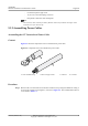
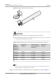
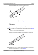
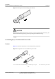
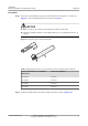
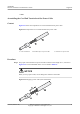
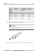
Table Of Contents
- About This Document
- Contents
- 1 AP2030DN Overview
- 2 AP Installation
- 3 Logging In to the AP
- 4 Hardware Failures
- 5 Appendix

Figure 5-3 Putting the heat shrink tubing onto the bare crimping terminal
Step 3 Put the OT terminal B onto the exposed conductor, and ensure that the OT terminal is in good
contact with the insulation coating C, as shown in Figure 5-3.
NOTICE
After the conductor is fed into the OT terminal, the protruding part of the conductor, or L2 in
Figure 5-3, must not be longer than 2 mm (0.08 in.).
Step 4 Crimp the joint parts of the bare crimping terminal and the conductor, as shown in Figure 5-4.
NOTE
The shapes of crimped parts may vary with the crimping dies.
Figure 5-4 Crimping the joint parts of the bare crimping terminal and the conductor (OT
terminal)
Step 5 Push the heat shrink tubing (A) toward the connector until the tube covers the crimped part,
and then use a heat gun to heat the tube, as shown in Figure 5-5.
AP2030DN
Hardware Installation and Maintenance Guide
5 Appendix
Issue 05 (2016-07-22) Huawei Proprietary and Confidential
Copyright © Huawei Technologies Co., Ltd.
29