AP Series Indoor Wireless LAN Access Points Quick Start Guide
Copyright © Huawei Technologies Co., Ltd. 2012. All rights reserved. No part of this document may be reproduced or transmitted in any form or by any means without prior written consent of Huawei Technologies Co., Ltd. Trademarks and Permissions and other Huawei trademarks are trademarks of Huawei Technologies Co., Ltd. All other trademarks and trade names mentioned in this document are the property of their respective holders.
Preface This document describes the hardware configuration, installation preparation, installation method, installation procedure, cable connection, and procedure for logging in to the indoor APs.
Documentation Obtaining You can visit http://enterprise.huawei.com to obtain the latest product documentations. Choose Support > Product > Enterprise Networking > Datacom Network > WLAN > Product Documentation, and then select the document of a specified version. NOTE You can select the document as required. For example, if you want to obtain AP7110DN-AGN documents, select AP7110DN-AGN.
Change History Changes between document issues are cumulative. Therefore, the latest document issue contains all the changes in previous issues. Change in Issue 01 (2012-10-31) Initial commercial release.
Device Introduction The Huawei AP series indoor wireless LAN access point provides eight models: AP3010DN-AGN, AP5010DN-AGN, AP5010SN-GN, AP6010DN-AGN, AP6010SN-GN, AP6310SN-GN, AP7110DN-AGN, and AP7110SN-GN. The indoor AP features high reliability, high security, simple network deployment, automatic AC discovery and configuration, and real-time management and maintenance.
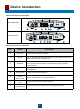
Device Introduction Table 2 Interfaces on indoor APs AP7110DN-AGN Console 7 ETH/PoE Default DC 12V 4 8 3 2 1 5 6 AP7110SN-GN Console 8 4 ETH/PoE Default DC 12V 3 2 1 5 6 Table 3 Interfaces on indoor APs No. Name 1 DC 12V Connected to the power adapter. 2 Default Press and hold down the Reset button for 3 seconds to restore the factory settings and restart the AP. 3 ETH/PoE 4 Console 5 Security slot Connected to the security lock. 6 2.
Installation Preparations 1. Safety Precautions WARNING Only the qualified personnel are permitted to install and remove the device and its accessories. Before installation and operation, read the safety precautions carefully. Take proper measures to prevent injuries and device damage. Place the device in a dry and flat position away from any liquid and prevent the device from slipping. Keep the device clean. Do not put the device and tools in the aisles. 2.
Installation Preparations 3. Device Accessories The following accessories are delivered together with indoor APs: AP3010DN, AP5010DN&SN: plastic wall-mounting bracket AP6010DN&SN, AP6310SN, AP7110DN&SN: sheet metal wallmounting bracket Expansion screws 4.
Installing the AP 1. Installation Flowchart Figure 1 Flowchart for installing an AP Start Check before installation To a T-rail Determine the installation location Against the ceiling Against the wall Fix the wall-mounting bracket to a T-rail Fix the wall-mounting bracket against the wall Fix the wall-mounting bracket against the ceiling Install the AP Connect the security lock to the lock hole Connect the cable End 2. Checking Before Installation Unpack the package.
Installing the AP 3. Determining the Installation Position When determining the AP installation position, comply with the following rules: Try to reduce the number of obstacles, such as walls, between the AP and user terminals. Install the AP away from electronic devices that can interfere the radio signal or make noises, such as the microwave oven. Install the AP in a hidden position that does not affect working and living of residents.
Installing the AP 4. Installing the AP NOTE The AP3010DN-AGN, AP5010DN-AGN, and AP5010SN-GN have plastic wall-mounting bracket delivered with them, so they can only be wall mounted. The AP6010DN-AGN, AP6010SN-GN, AP6310SN-GN, AP7110DN-AGN, and AP7110SN-GN have sheet metal wall-mounting bracket delivered with them, so they can be wall mounted, ceiling mounted, or T-rail mounted indoors. The procedures for installing all models of indoor APs are the same unless otherwise stated.
Installing the AP Against the Ceiling 1. Fix a clip holder at the rear side of the AP with two M3*6 screws. The wall-mounting bracket is fixed at the ceiling, and the AP is hung on the bracket. The clip holder prevents the AP from dropping. 2 1 1. M3*6 screw 2. Clip holder 2. Remove the ceiling, determine locations of mounting holes based on the distance between two installation holes, use the hammer drill to drill holes, and fix the wall-mounting bracket to the ceiling. 2 1 UP UP 35mm 3 1.
Installing the AP 3. Align the cucurbit holes at the rear side of the AP with four screws on the wall-mounting bracket and secure the AP. 5G 5G 5G To a T-rail 1. Fix a clip holder at the rear side of the AP with two M3*6 screws. For details, see step 1 in Against the Ceiling. 2. Remove the two ceilings around the T-rail.
Installing the AP 5. Installing the Security Lock NOTE You need to purchase the security lock. The device provides a lock hole. You can lock the device to an immovable object to ensure security. The detailed procedures are as follows: 1) Fix the cable of the security lock to a fixed object around. 2) Plug the locking piece into the security keyhole on the device and lock it. 2 1 1. Lock hole 2. Security lock 6.
Installing the AP Table 6 Appearance of indoor APs (front view) AP7110DN-AGN Console 1 3 ETH/PoE Default DC 12V 4 5 2 AP7110SN-GN Console 3 ETH/PoE Default DC 12V 4 5 2 Table 7 Cables of indoor APs No. Cable Description 1 5 GHz antenna cable Connects to the 5 GHz antenna for transmitting and receiving signals. 2 2.4 GHz antenna cable Connects to the 2.4 GHz antenna for transmitting and receiving signals.
Installing the AP Table 8 Pin assignment X1 Pin Wire Color X2 Pin 1 White and orange 1 2 Orange 2 3 White and green 3 4 Blue 4 5 White and blue 5 6 Green 6 7 White and brown 7 8 Brown 8 NOTE The antennas of AP6310SN-GN, AP7110DN-AGN and AP7110SN-GN used must comply with local laws. In North America or other regions that Require FCC certification, AP6310SN-GN must use W5030H antennas from Pulse. AP7110DN-AGN and AP7110SN-GN must use SL15870A or TT-2403-6W1 antennas.
Power-on The indoor AP supports the DC power supply and PoE power supply. You can select the power supply mode as required. 1. Checking Before Power-on After the AP installation is complete, you should check the following items before power-on: When the DC power supply is used, ensure that the DC power supply is properly grounded. When the PoE power supply is used, ensure that the PoE power supply is properly grounded. Indoor APs can be either powered on by the PoE or DC power supply.
Power-on Table 10 Indicator status of the AP6310SN-GN Indicator Information Type Startup status SYS Link Wireless Steady green NA NA The device is being started. Blinking green NA NA The system is working properly. Steady red NA NA The system fails to load the DRAM or system software. Off 0.5Hz Off Blinking green Off Running and connection 0.5Hz Steady or Blinking green 18 Blinking green Description The system is working properly. However, the Ethernet is not connected.
Power-on Table 11 Indicator status of the AP7110SN-GN and AP7110DN-AGN Information Type Startup status SYS Link Wireless Steady green NA NA The device is being started. Blinking green NA NA The system is working properly. Steady red NA NA The system fails to load the DRAM or system software. The system is working properly. However, the Ethernet is not connected. Radios are disabled and no user is connected to the AP. Off The system is working properly, but the Ethernet is not connected.
Logging In to the AP After an AP is powered on, you can log in to the AP using the following methods. 1. Logging In to the AP Through the Console Port 2. Logging In to the AP Using Telnet 1. Logging In to the AP Through the Console Port This section describes how to log in to the AP through the console port. After logging in to the AP, you can configure the AP using commands. Procedure Step 1 Connect a PC to the AP with a console cable.
Logging In to the AP Step 4 Click Restore Defaults, select 9600 bit/s from the Bits per second drop-down list box, and click OK, as shown in Figure 1-3. Figure 1-3 Setting communication parameters Step 5 Press Enter on the subsequent dialog boxes until the command line prompt of the user view, such as , is displayed. You can run commands to configure the AP. Enter a question mark (?) whenever you need help. ----End 2.
Logging In to the AP NOTE Run the exit command to exit from the Telnet window. When the system fails to exit from the Telnet window: If you logged in to the AP from an AC or a switch, press Ctrl+T to return to the AC or switch view. This operation does not affect the AP operation. If you logged in to the AP from a PC, directly close the Telnet window. This operation does not affect the AP operation.
Appendix 1.
Appendix 3. Warranty Card Warranty Card Thank you for choosing HUAWEI Technologies Co., Ltd-a leading telecom solution provider. To get better services, please read this warranty card carefully, fill in the required information and preserve this card in good condition. Your Name Address/Postal Code Telephone Product Type Product Serial Number. Purchase Date. Invoice Number. Dealer's Name Dealer's Address/Telephone Preserve well.