SmartAX MT882 ADSL Router User Manual HUAWEI TECHNOLOGIES CO., LTD.
SmartAX MT882 ADSL Router User Manual Issue 01 Date 2007-09-06 No. 103074 Huawei Technologies Co., Ltd. Address: Huawei Industrial Base Bantian, Longgang Shenzhen 518129 People's Republic of China Website: http://www.huawei.com Email: terminal@huawei.com Copyright © Huawei Technologies Co., Ltd. 2007. All rights reserved. No part of this document may be reproduced or transmitted in any form or by any means without prior written consent of Huawei Technologies Co., Ltd.
Federal Communications Commission (FCC) Statement This device complies with part 15 of the FCC Rules. Operation is subject to the following two conditions: (1) This device may not cause harmful interference, and (2) this device must accept any interference received, including interference that may cause undesired operation. Safety Precautions z z z z z z z z z z z z General Requirements: Before you install and use the device, read these safety precautions carefully and observe them during operation.
z z z z z z z z z z z z z z z Keep the device far away from any heat source or bare fire, such as a candle or an electric heater. Keep the device far away from any household appliance with strong magnetic field or electromagnetic field, such as a microwave oven or a refrigerator. Operating Requirements: Do no let a child operate the device without guidance. Do not let a child play with the device or any accessory. Swallowing the accessories may lead to peril.
z Keep the power plug clean and dry. Using a dirty or wet power plug may lead to electric shock or other perils.
文档名称 文档密级 Note: This equipment has been tested and found to comply with the limits for a Class B digital device, pursuant to part 15 of the FCC Rules. These limits are designed to provide reasonable protection against harmful interference in a residential installation. This equipment generates, uses and can radiate radio frequency energy and, if not installed and used in accordance with the instructions, may cause harmful interference to radio communications.
Table of Contents Chapter 1 Introduction .....................................................................1 1.1 Functions and Features.........................................................1 1.2 Appearance ...........................................................................1 1.2.1 Front Panel .................................................................2 1.2.2 Rear Panel..................................................................4 Chapter 2 Installation of the MT882 ..................
3.3.2 Steps.........................................................................28 3.4 Configuring the PPPoE Mode .............................................29 3.4.1 Preparation ...............................................................30 3.4.2 Steps.........................................................................31 3.5 Configuring the PPPoA Mode .............................................33 3.6 Configuring the RFC2684B Mode .......................................33 3.6.1 Preparation ..
Chapter 1 Introduction This chapter describes the functions and the appearance of the SmartAX MT882 ADSL Router (hereinafter referred to as the MT882). 1.1 Functions and Features The MT882 is a type of Asymmetric Digital Subscriber Line (ADSL) terminal. Using the MT882 and a telephone line, you can enjoy data, video and audio services at a high speed. The features of the MT882 are: z High transmission rate: The maximum downlink transmission rate is 24 Mbit/s. The maximum uplink transmission rate is 1.
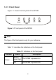
1.2.1 Front Panel Figure 1-1 shows the front panel of the MT882. Figure 1-1 Front panel of the MT882 Note: The figure of the front panel is only for your reference. Table 1-1 describes the indicators on the front panel. Table 1-1 Indicators on the front panel Indicator Power Status Description Steady green light The MT882 is powered on. Off The MT882 is powered off.
Indicator ADSL LINK ADSL ACT LAN Status Description Blinking green light The MT882 is being activated. On The MT882 is activated. Blinking orange light The built-in PPP dial-up software is dialing. Steady orange light The built-in PPP dial-up software completes dialing successfully. Off The telephone line is not connected or the MT882 is preparing for the next activation. Blinking green light Data is being transmitted over the ADSL interface.
Indicator USB Status Description Steady green light The USB interface is connected. Blinking green light Data is being transmitted over the USB interface. Off The USB interface is not connected. Note: If the MT882 fails to activate, it tries again after one minute. The ADSL LINK indicator is off during this period. 1.2.2 Rear Panel Figure 1-2 shows the rear panel of the MT882.
Note: The figure of the rear panel is only for your reference. Table 1-2 describes the interfaces and buttons on the rear panel. Table 1-2 Interfaces and buttons on the rear panel Interface/Button Description ADSL It connects with the Modem interface of a splitter. USB It connects with a computer. Ethernet It connects with a computer or a switch. It restores the default settings of the MT882. Reset Once you press this button, all your customized settings will be lost.
Chapter 2 Installation of the MT882 This chapter introduces the installation of the MT882. 2.1 Preparation Before installing the MT882, prepare the following components: z Ethernet card: The MT882 communicates with a computer through an Ethernet card. Make sure that an Ethernet card is installed on the computer before connecting the MT882 with the computer. z Splitter (optional): A splitter can separate the data signals from the voice signals being transmitted over a telephone line.
Figure 2-1 Connecting the MT882 (1) PC (4) Splitter (7) RJ-11 telephone line (2) Phone (5) RJ-11 telephone line (3) RJ-11 telephone line (6) Phone jack (8) MT882 (9) RJ-45 Ethernet cable Caution: Before connecting the MT882, power off the MT882 and the computer.
Operation: 1) Connect the interfaces of the splitter with other devices by using a telephone line: z LINE interface --> telephone jack on the wall z MODEM interface --> ADSL interface of the MT882 z PHONE interface --> telephone 2) Connect the Ethernet interface of the MT882 with the Ethernet interface of the computer by using a straight through cable. 3) Connect the MT882 to a power socket by using the provided power adapter. 4) Press the Power button of the MT882 to power on the MT882.
3) Execute the following commands: # cd usb_driver_for_linux # make # make install Note: usb_driver_for_linux is the file name where you store the driver. 4) Edit file located on /etc/rc.d/rc.local, append two lines as below: insmod /usr/local/lib/trendchip/trendchip.o &>/dev/null & ifconfig eth1 192.168.1.2 up &>/dev/null & Note: This step will make trendchip's driver be loaded automatically when system startup. 5) Create a new file named ifcfg-eth1 in /etc/sysconfig/networking/device/.
PEERDNS=yes GATEWAY=192.168.1.1 TYPE=Ethernet DEVICE=eth1 HWADDR=00:aa:bb:cc:00:01 BOOTPROTO=none NETMASK=255.255.255.0 ONBOOT=no IPADDR=192.168.1.2 NETWORK=192.168.1.0 BROADCAST=192.168.1.255 Note: This step will create a new Ethernet interface eth1 and configure this properties. 6) Create or modify the file named resolv.conf in /etc/sysconfig/networking/profiles/default/.
Note: This step is configuring your DNS setting. Note that is the actual IP address of the DNS which you should get from your ISP. 7) Create a new file named ifcfg-eth1 in /etc/sysconfig/network-scripts/. Add the following content: DEVICE=eth1 BOOTPROTO=none BROADCAST=192.168.1.255 IPADDR=192.168.1.2 NETMASK=255.255.255.0 NETWORK=192.168.1.0 ONBOOT=no USERCTL=no PEERDNS=no GATEWAY=192.168.1.1 TYPE=Ethernet 8) Reboot PC and then plug and power on your ADSL modem. 2.3.
1) Run the MAC USB driver from the CD-ROM provided with MT882, and decompress it. 2) Double-click the Installer to start the installation. 3) Click Next to display the Authenticate page.
4) Enter the name and password of the administrator, and click OK. 5) Read the information carefully and click Accept.
6) Select a destination folder to install and click Next. 7) Select Restart now and click Finish to restart your computer.
2.3.3 Installing the USB Driver in Windows Vista/XP/2K To install the USB driver on a Windows system, do as follows. 1) Connect the MT882 with your computer by using an USB cable. 2) 3) 4) Power on the MT882. Double-click Setup.exe on the CD-ROM provided with MT882 to display the Setup Wizard window, and you will see the Hello page. Click Next to continue the installation.
5) Select Typical and Click Next.
6) Click Next to continue the installation.
7) Click Continue Anyway to continue the installation.
8) Click Finish. 2.4 Setting Up the Configuration Environment You can configure the MT882 through the Web setup page. This chapter describes how to set up the configuration environment of the MT882. 2.4.1 Planning the Parameters Before setting up the configuration environment, plan the following parameters.
Table 2-1 Parameters for the configuration environment Item Description Username and password of the administrator of the MT882 Default: LAN IP address and subnet mask of the MT882 Default: IP address and subnet mask of the computer z z z z Username: admin Password: admin IP address: 192.168.1.1 Subnet mask: 255.255.255.0 Make sure that the IP address of the computer is in the same network segment as the LAN IP address of the MT882. For example: z z IP address: 192.168.1.100 Subnet mask: 255.255.
Step To... Do... Taking Internet Explorer 6.0 as an example: 2 Check and ensure that the proxy server is not used 1) 2) 3) 4) 1) 3 Log in to the Web setup page 2) 3) Launch the Internet Explorer. Choose Tools > Internet Options... to display the Internet Options dialog box. Choose the Connections tab and click LAN Settings.... Deselect the Use a proxy server for your LAN (These settings will not apply to dial-up or VPN connections) checkbox.
z The navigation tree: On the left of the page, it allows you to access different setup pages. z Configuration area: On the right of the page, it displays the configuration data.
Chapter 3 Service Configuration This chapter introduces how to configure the MT882. Note: The figures in the following configuration operations are only for your reference. 3.1 Configuration Method 3.1.1 Protocol Model Figure 3-1 shows the protocol model for the connection between the MT882 and the DSLAM at the office end.
The data between the MT882 and the DSLAM are transmitted in the Asynchronous Transfer Mode (ATM). To configure the MT882 for different services, you need to configure the Permanent Virtual Channel (PVC) and other parameters. 3.1.2 Steps The steps to configure the service modes are as follows. Step 1 To... Establish the configuration environment Do... See section 2.4 "Setting Up the Configuration Environment.
3.2 Service Modes of the MT882 The MT882 supports multiple service modes. To choose a proper service mode, you need to take the DSLAM settings into consideration. Table 3-1 lists the available service modes. Table 3-1 Service modes of the MT882 Service Mode Working Method z Bridge z z z PPPoE z z z PPPoA z Configuration Take the MT882 as bridge equipment. Use the PPP dial-up software of the computer to dial a number. Refer to 3.3 "Configuring the Pure Bridge Mode". Take the MT882 as a router.
Service Mode Working Method z z RFC2684B z z z RFC2684(IPoA) z Configuration Take the MT882 as a router. The MT882 obtains an IP address from DHCP server or uses the static public IP to access the Internet. Use the RFC2684B encapsulation mode to encapsulate the packets. Refer to 3.6 "Configuring the RFC2684B Mode". Take the MT882 as a router. The MT882 uses the static public IP address to access the Internet. Use the IPoA encapsulation mode to encapsulate the packets. Refer to 3.
3.3 Configuring the Pure Bridge Mode In the pure bridge mode, the MT882 functions as a bridge. You need to install the PPP dial-up software in your computer to access the Internet. This section describes how to configure the MT882 to work in the pure bridge mode. It also describes how to configure your computer to access the network through the MT882. 3.3.1 Preparation Table 3-2 lists the configuration items.
3.3.2 Steps You need to configure the MT882 and your computer in turn. I. Configuring the MT882 The steps are as follows: 1) Log in to the Web setup page of the MT882. For details, see section 2.4 "Setting Up the Configuration Environment." 2) Choose Basic > WAN Setting in the navigation tree to 3) display the WAN configuration page. Select the PVC, which needs configuring, from the PVC drop-down menu of the WAN configuration page. 4) Select Bridge from the Mode drop-down menu.
II. Configuring Your Computer After configuring the MT882, install the PPP dial-up software in your computer to access the network. The Windows XP (Professional) operating system has built-in PPPoE dial-up software. Take the Windows XP system as an example, the steps to set up a PPP dial-up connection are as follows: 1) Choose Start > All Programs > Accessories > Communications > Network Connections. 2) Click Create a new connection in the displayed page.
This chapter describes how to configure the MT882 to work in the PPPoE mode. It also describes how to configure your computer to access the network through the MT882. 3.4.1 Preparation Table 3-3 lists the configuration items.
Note: After the DHCP server is enabled, the MT882 can assign a private IP address to the computer. 3.4.2 Steps I. Configuring the MT882 The steps are as follows: 1) Log in to the Web setup page. For details, see section 2.4 "Setting Up the Configuration Environment." 2) Choose Basic > WAN Setting in the navigation tree to display the WAN configuration page. 3) Choose the PVC to be configured and click the editing icon. 4) Select Routing in the PVC Mode field.
Figure 3-3 Configuring the PPPoE mode 32
6) Click Submit. 7) Choose Basic > DHCP in the navigation tree to display the DHCP configuration page. 8) Choose DHCP Server and click Submit. 9) Choose Tools > Reboot in the navigation tree. 10) Select Current Settings in the Reboot page. Click Restart to save the configuration. II. Configuring Your Computer Configure the Ethernet card on your computer, so that your computer can automatically obtain such information as the IP address, gateway and Domain Name Server (DNS). 3.
3.6.1 Preparation Table 3-4 shows the configuration preparation.
1) Log in to the Web setup page. For details, see section 2.4 "Setting Up the Configuration Environment." 2) Choose Basic > WAN Setting in the navigation tree to display the WAN configuration page. 3) Choose the PVC to be configured and click the editing icon. 4) Select Routing in the PVC Mode field. 5) Select RFC2684B from the Encapsulation drop-down menu. Set the Active to Yes. Configure relevant parameters in Figure 3-4 according to the values in the Table 3-4.
Figure 3-4 Configuring the RFC2684B mode 6) Click Submit. 7) Choose Basic > DHCP in the navigation tree to display the DHCP configuration page. 8) Choose DHCP Server in the DHCP configuration page. Click 9) Submit. Select Tools > Reboot in the navigation tree.
10) Select Current Settings in the Reboot page. Click Submit to save the configuration. II. Configuring Your Computer Configure the Ethernet card on your computer, so that your computer can automatically obtain such information as the IP address, gateway and DNS. 3.7 Configuring the RFC2684(IPoA) Mode It is similar to configure the RFC2684(IPoA) mode as to configure the RFC2684B mode.
Chapter 4 Other Configurations 4.1 Changing the LAN IP Address You can access the Web setup page of the MT882 through the LAN IP address of the MT882. The MT882 has a default LAN IP address. To change it, follow the steps described below: 1) Log in to the Web setup page of the MT882. For details, see section 2.4 "Setting Up the Configuration Environment." 2) Choose Basic > LAN Setting in the navigation tree to display the LAN configuration page. 3) Enter the IP address and the subnet mask.
4.2 Changing the Administrator Password The Web manager of the MT882 provides the password protection function to prevent illegal users from changing the configuration of the MT882. The username and the password of the MT882 administrator can be changed as follows: 1) Log in to the Web setup page of the MT882. For details, see section 2.4 "Setting Up the Configuration Environment." 2) Choose Tools > System Management in the navigation tree to display the system management page.
1) Find the Reset button on the rear panel of the MT882. 2) Use a pin to press the Reset button and then release it. II. Using the Web Manager The steps are as follows: 1) Choose Tools > Reboot in the navigation tree to display the Reboot page. 2) Choose Factory Default Settings. 3) Click Restart. 4.4 Firmware Upgrade Select Tools > Firmware Upgrade in the navigation tree. Input the correct path of the upgrade file and then click Upload. It may take a few minutes to finish the upgrade.
Chapter 5 Troubleshooting 5.1 Fixing Common Problems Problem Solution z The Power indicator is not on z z z The ADSL LINK indicator is not on z z z z z The LAN indicator is not on z Ensure that the power adapter matches the MT882. Ensure that the MT882 is connected to the power supply properly. Ensure that the Power button is pressed. Ensure that the ADSL line is connected properly. Ensure that the telephone line works normally. Run the check by using a telephone.
Problem Solution card. Note: "Network adapter" refers to a network interface card. In this context, it is the Ethernet card of your computer. z z z The Internet cannot be accessed z z z z Ensure that all the previous problems are addressed. Ensure that the PVC parameters provided by the ISP are not changed. Otherwise, restore the default settings. Ensure that the dial-up software is correctly installed and properly set in your computer. Ensure that you have entered the right username and password.
2) Keep the MT882 away from appliances with strong electric fields or magnetic fields, such as a microwave oven and a refrigerator. 3) Make sure that no telephone or fax machine is connected directly to the ADSL line. 4) Replace the Ethernet card using the Industry Standard Architecture (ISA) bus with a 10/100M Ethernet card using the Peripheral Component Interconnect (PCI) bus. Install the latest driver. 5) Find help on http://www.huawei.com. II.
Chapter 6 Technical Specifications Main Technical Specifications ITU G.992.1 (G.dmt) Annex A ADSL standard Standard ITU G.994.1 (G.hs) ANSI T1.413 Issue 2 ADSL2 standard ITU G.992.3 (G.dmt.bis) Annex A ADSL2+ standard ITU G.992.5 Annex A z G.dmt T1.413 Data transfer rate z z G.992.5 (ADSL2+) z 44 The maximum downlink rate is 8 Mbit/s The maximum uplink rate is 896 kbit/s The maximum downlink rate is 24 Mbit/s The maximum uplink rate is 1.
Physical Features and Environment Requirements Power consumption <5W Power adapter output 12 V AC 0.
Chapter 7 Appendix 7.1 Default Settings 7.1.1 Common Default Parameters Item Default Value Username of administrator admin Password of administrator admin IP address 192.168.1.1 Subnet mask 255.255.255.0 DHCP mode Server NAT Disabled 7.1.2 Default PVC Parameters Sequence No.
Sequence No.
7.
PCI Peripheral Component Interconnect PPP Point-to-Point Protocol PPPoA PPP over ATM PPPoE PPP over Ethernet PVC Permanent Virtual Channel V VCI Virtual Channel Identifier VPI Virtual Path Identifier W WAN Wide Area Network 49
HUAWEI TECHNOLOGIES CO., LTD. Huawei Industrial Base Bantian, Longgang Shenzhen 518129 People's Republic of China www.huawei.com No.