Huawei AP4030DN Hardware Installation and Maintenance Guide Issue 02 Date 2015-05-18 HUAWEI TECHNOLOGIES CO., LTD.
Copyright © Huawei Technologies Co., Ltd. 2015. All rights reserved. No part of this document may be reproduced or transmitted in any form or by any means without prior written consent of Huawei Technologies Co., Ltd. Trademarks and Permissions and other Huawei trademarks are trademarks of Huawei Technologies Co., Ltd. All other trademarks and trade names mentioned in this document are the property of their respective holders.
Huawei AP4030DN Hardware Installation and Maintenance Guide Contents Contents 1 AP Overview .................................................................................................................................. 1 1.1 Device Structure ........................................................................................................................................................... 1 1.2 Indicator Description ................................................................................
Huawei AP4030DN Hardware Installation and Maintenance Guide Contents 5.2 Environmental Requirements for Device Operation ................................................................................................... 66 5.2.1 Environmental Requirements for an Equipment Room ........................................................................................... 66 5.2.2 Requirements for Power Supply ....................................................................................................
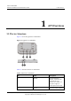
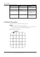
Huawei AP4030DN Hardware Installation and Maintenance Guide 1 AP Overview 1 AP Overview 1.1 Device Structure Figure 1-1 show the appearance of AP4030DN Figure 1-1 Appearance of AP4030DN Table 1-1 describes interfaces on AP4030DN. Table 1-1 Interfaces on AP4030DN No. Name Description 1 GE/PoE 10/100/1000M bit/s interface: connects to the wired Ethernet. The interface can connect to a PoE power supply to provide power for the AP.
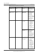
Huawei AP4030DN Hardware Installation and Maintenance Guide No. 1 AP Overview Name Description a 12 V power adapter to the AP. 3 Security slot Connects to a security lock. 4 Console Console interface: connects to a maintenance terminal for AP configuration and management. 5 Default Reset button: restores factory settings if you hold down the button more than 3s. 1.2 Indicator Description AP4030DN provide only a single indicator, as shown in Figure 1-2.
Huawei AP4030DN Hardware Installation and Maintenance Guide 1 AP Overview Table 1-2 Description of the indicator on the AP4030DN Type Color Status Description Default status after power-on Green Steady on The AP is just powered on and the software is not started yet. Software startup status Green Steady on after blinking once After the system is reset and starts uploading the software, the indicator blinks green once.
Huawei AP4030DN Hardware Installation and Maintenance Guide Type 1 AP Overview Color Status Description link is established). Fault Red The AP fails to go online on the AC (the CAPWAP link disconnects). A fault that affects services has occurred, such as a DRAM detection failure or system software loading failure. The fault cannot be automatically rectified and must be rectified manually. Steady on 1.
Huawei AP4030DN Hardware Installation and Maintenance Guide 1 AP Overview Item Description increases 220 m. Storage temperature -40°C to +70°C Operating humidity 5% to 95% (non-condensing) Ingress Protection Rating IP41 Atmospheric pressure 70kPa to 106kPa 1.4 Ordering Information To place an order, contact the Huawei local office.
Huawei AP4030DN Hardware Installation and Maintenance Guide 2 AP Installation 2 AP Installation 2.1 Preparing for Installation This section describes safety precautions and tool preparations for AP installation. Safety Precautions Take proper measures to prevent injuries and device damage. Place the device in a dry and flat position away from any liquid and prevent the device from slipping. Keep the device clean. Do not put the device and tools in the aisles.
Huawei AP4030DN Hardware Installation and Maintenance Guide 2 AP Installation Diagonal pliers RJ45 crimping tool Wire stripper Network cable tester Multimeter Inner hexagon wrench (M6) Ladder Adjustable wrench ESD gloves Level Rubber mallet 2.2 Installation Flowchart The following figure shows the process for installing an AP. Issue 02 (2015-05-18) Huawei Proprietary and Confidential Copyright © Huawei Technologies Co., Ltd.
Huawei AP4030DN Hardware Installation and Maintenance Guide 2 AP Installation Figure 2-1 Installation flowchart Start Check before installation Determine the installation location To a T-rail Fix the wall-mounting bracket to a T-rail Connect the cable Against the ceiling Against the wall Fix the wall-mounting Fix the wall-mounting bracket against the wall bracket against the ceiling Install the AP Connect the security lock to the lock hole Check after installation Power on the AP End 2.
Huawei AP4030DN Hardware Installation and Maintenance Guide 2 AP Installation 2.4 Determining the Installation Position When determining the AP installation position, comply with the following rules: Try to reduce the number of obstacles, such as walls, between the AP and user terminals. Install the AP away from electronic devices that can cause radio interference, such as the microwave oven. Install the AP in a hidden position that does not affect daily lives and work of residents.
Huawei AP4030DN Hardware Installation and Maintenance Guide 2 AP Installation 2. Use a 6 mm drill bit to drill 25 mm to 30 mm deep holes in the drilling positions. Hammer the expansion tubes into the holes until the expansion tubes are completely embedded into the wall. 3. Fix the mounting bracket to the wall and use the Phillips screwdriver to fasten three expansion screws into the expansion tubes. 4.
Huawei AP4030DN Hardware Installation and Maintenance Guide 2 AP Installation 2.5.2 Ceiling Mounting 1. Remove a ceiling tile, determine locations of mounting holes based on the distance between two installation holes on the mounting bracket, use a hammer drill to drill holes on the ceiling tile, and fix the mounting bracket to the ceiling tile. 1. Ceiling tile 2. Issue 02 (2015-05-18) 2. Adjustable buckle 3.
Huawei AP4030DN Hardware Installation and Maintenance Guide 2 AP Installation The screws provided for ceiling-mounting of APs are 30 mm long and can be used to fix an AP on a ceiling not thicker than 15 mm. To install APs on thicker ceilings, you need to purchase longer screws. Ensure that the AP is correctly installed on the mounting bracket and there must be 200 mm space above and around the AP for maintenance. 2.5.3 T-rail Mounting 1.
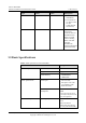
Huawei AP4030DN Hardware Installation and Maintenance Guide 2 AP Installation Before fixing the adjustable buckle with a screw, you need to adjust the buckle to a proper position based on the T-rail width. Ensure that the AP is correctly installed on the mounting bracket and there must be 200 mm space above and around the AP for maintenance. 2.6 Connecting Cables Figure 2-3 show the appearance of AP4030DN. Figure 2-3 Appearance of AP4030DN Table 2-2 Cable connections No.
Huawei AP4030DN Hardware Installation and Maintenance Guide 2 AP Installation No. Cable Description 1 Network cable The network cables used are category-5 enhanced or higher twisted pairs. Ensure that the AP is connected to the Ethernet using the Ethernet cable that works properly. If the Ethernet cable is not working properly, for example, RJ45 connectors are short-circuited, the AP may fail to be powered on or fail to work.
Huawei AP4030DN Hardware Installation and Maintenance Guide 1. Fasten the cable of the security lock to an immovable object around. 2. Insert the security lock into the security slot and lock it. 2 AP Installation You need to purchase the security lock separately. 2.8 Checking the AP After Installation Table 2-3 shows the items to be checked after AP installation is complete. Table 2-3 AP installation checklist No. Check Item 1 The AP is installed by strictly following the design draft.
Huawei AP4030DN Hardware Installation and Maintenance Guide 2 AP Installation Do not frequently power on and off an AP. Issue 02 (2015-05-18) Huawei Proprietary and Confidential Copyright © Huawei Technologies Co., Ltd.
Huawei AP4030DN Hardware Installation and Maintenance Guide 3 Logging In to the AP 3 Logging In to the AP 3.1 Logging In to the AP Through the Console Port This section describes how to log in to the AP through the console port. After logging in to the AP, you can configure the AP using commands. 1. Connect a PC to the AP using a console cable. Connect the RJ45 connector to the console port of the AP and the DB9 connector to the serial port of a PC.
Huawei AP4030DN Hardware Installation and Maintenance Guide 3 Logging In to the AP For the FIT AP, the default user name and password are respectively admin and admin@huawei.com. For the FAT AP, the default password is admin@huawei.com When you log in to the system again in password authentication mode, enter the password that is set during the initial login. You can run commands to configure the device. Enter a question mark (?) whenever you need help. 3.
Huawei AP4030DN Hardware Installation and Maintenance Guide 3 Logging In to the AP Figure 3-1 PuTTY Configuration page 3. Click Open. Enter the user name and password at the prompt, and press Enter. You have logged in to the device. (The following information is only for reference.) login as: admin Sent username "admin" admin@169.254.1.1's password: It is recommended that you change the initial user name and password after login. 3.
Huawei AP4030DN Hardware Installation and Maintenance Guide 3 Logging In to the AP The web management system is enabled on the AP before delivery. The default IP address of the web management system is 169.254.1.1 and the mask is 255.255.0.0. The web management system provides a default user account, with the user name admin and password admin@huawei.com. You are advised to change the user name and password on your first login.
Huawei AP4030DN Hardware Installation and Maintenance Guide 4 Hardware Failures 4 Hardware Failures 4.1 A Device Fails to Be Powered On Fault Description The SYS indicator of a device is off. Possible Causes Power Supply Mode Possible Cause Power supply using a power module The power switch on the device is turned off. The power cable is not securely connected to the device. The power supply unit has failed.
Huawei AP4030DN Hardware Installation and Maintenance Guide 4 Hardware Failures Troubleshooting Procedure Power Supply Mode Troubleshooting Procedure Power supply using a power module 1. Check that the power switch is on. 2. Check that the power cable is securely connected to the device. 3. Check whether the power supply is normal. Replace the power adapter with a normal one. If the device is powered on, the original power adapter is faulty.
Huawei AP4030DN Hardware Installation and Maintenance Guide 5 Appendix 5 Appendix 5.1 On-site Cable Assembly and Installation 5.1.1 Cable Assembly Precautions Checking the Appearance of Cables If the cable jacket or insulation is visibly dirty, clean it before assembly. If the jacket or insulation of a cable has visible damage, irreparable scuffing, or other defects, do not use the cable. If the shield layer of a cable is damaged, do not use the cable.
Huawei AP4030DN Hardware Installation and Maintenance Guide 5 Appendix − When stripping the jackets of cables, avoid damaging the shield layers (braid or aluminum foil), insulation, core conductors, and other jackets that do not need to be stripped. − After assembling cables, cut all visible cross sections of jackets to ensure that the cross sections are arranged neatly. − Do not touch the core conductors of cables with your hands.
Huawei AP4030DN Hardware Installation and Maintenance Guide 5 Appendix Figure 5-2 Stripping a power cable (OT terminal) When you strip a power cable, do not damage the conductor of the cable. If the bare crimping terminal is not provided by Huawei, the value of L1 is 1 mm (0.04 in.) to 2 mm (0.08 in.) greater than the value of L. Table 5-1 Mapping between the cross-sectional area of the conductor and the value of L1 Cross-Section al Area of Conductor (mm2(in.2)) Value of L1 (mm(in.
Huawei AP4030DN Hardware Installation and Maintenance Guide 5 Appendix Figure 5-3 Putting the heat shrink tubing onto the bare crimping terminal Step 3 Put the OT terminal B onto the exposed conductor, and ensure that the OT terminal is in good contact with the insulation coating C, as shown in Figure 5-3. After the conductor is fed into the OT terminal, the protruding part of the conductor, or L2 in Figure 5-3, must not be longer than 2 mm (0.08 in.).
Huawei AP4030DN Hardware Installation and Maintenance Guide 5 Appendix Figure 5-5 Heating the heat shrink tubing (OT terminal) Stop heating the shrink tubing when the connector is securely locked in the shrink tubing. Do not heat the shrink tubing too long to damage the insulation coating. ----End Assembling the JG Terminal and Power Cable Context Figure 5-6 shows the components of a JG terminal and a power cable. Figure 5-6 Components of a JG terminal and a power cable A.
Huawei AP4030DN Hardware Installation and Maintenance Guide 5 Appendix Procedure Step 1 Based on the cross-sectional area of the cable conductor, strip a part of the cable. The L-long conductor is exposed, as shown in Figure 5-7. The recommended values of L are listed in Table 5-2. When you strip a power cable, do not damage the conductor of the cable. If the bare crimping terminal is not provided by Huawei, you can adjust the value of L as required.
Huawei AP4030DN Hardware Installation and Maintenance Guide 5 Appendix Figure 5-8 Putting the heat shrink tubing onto the bare crimping terminal Step 3 Put the bare crimping terminal onto the exposed conductor, and ensure that the bare crimping terminal is in good contact with the insulation of the power cable, as shown in Figure 5-8. Step 4 Crimp the joint parts of the bare crimping terminal and the conductor, as shown in Figure 5-9.
Huawei AP4030DN Hardware Installation and Maintenance Guide 5 Appendix Figure 5-10 Heating the heat shrink tubing (JG terminal) ----End Assembling the Cord End Terminal and the Power Cable Context Figure 5-11 shows the components of a cord end terminal and a power cable. Figure 5-11 Components of a cord end terminal and a power cable A. Cord end terminal B. Insulation layer of a power cable C.
Huawei AP4030DN Hardware Installation and Maintenance Guide 5 Appendix When you strip a power cable, do not damage the conductor of the cable. Figure 5-12 Stripping a power cable (cord end terminal) Table 5-3 Mapping between the cross-sectional area of the conductor and the value of L1 Cross-Section al Area of Conductor (mm2(in.2)) Value of L1 (mm(in.)) Cross-Sectional Area of Conductor (mm2(in.2)) Value of L1 (mm(in.)) 1 (0.002) 8 (0.31) 10 (0.015) 15 (0.59) 1.5 (0.002) 10 (0.39) 16 (0.
Huawei AP4030DN Hardware Installation and Maintenance Guide 5 Appendix Figure 5-13 Put the cord end terminal onto the conductor Step 3 Crimp the joint parts of the cord end terminal and the conductor, as shown in Figure 5-14. Figure 5-14 Crimping the cord end terminal and the conductor Step 4 Check the maximum width of the tubular crimped terminal. The maximum width of a tubular crimped terminal is listed in Table 5-4.
Huawei AP4030DN Hardware Installation and Maintenance Guide 5 Appendix Cross-Sectional Area of Tubular Terminal (mm2(in.2)) Maximum Width of Crimped Terminal W1 (mm(in.)) 16 (0.025) 6 (0.24) 25 (0.039) 8.7 (0.34) 35 (0.054) 10 (0.39) ----End 5.1.3 Assembling Ethernet Cables Assembling the Shielded RJ45 Connector and Ethernet Cable Context Figure 5-15 shows the components of an RJ45 connector and a shielded Ethernet cable. Figure 5-15 Shielded RJ45 connector and cable A. Jacket of connector B.
Huawei AP4030DN Hardware Installation and Maintenance Guide 5 Appendix Figure 5-16 Fit the jacket of the connector onto the Ethernet cable Step 2 Remove a 30 mm (1.18 in.) long section of the jacket, cut off the nylon twine inside the jacket, and cut a no more than 5 mm (0.20 in.) cleft in the jacket, as shown in Figure 5-17. When you remove a section of the jacket, do not damage the shield layer of the twisted-pair cable.
Huawei AP4030DN Hardware Installation and Maintenance Guide 5 Appendix Figure 5-18 Fitting the metal shell onto the twisted-pair cable Step 4 Fit the metal shell onto the twisted-pair cable until the shield layer is covered completely. Along the edge of the metal shell, cut off the aluminum foil shield layer and ensure that there is no surplus copper wire. The exposed twisted-pair cable is about 20 mm (0.79 in.) long, as shown in Figure 5-19.
Huawei AP4030DN Hardware Installation and Maintenance Guide 5 Appendix Figure 5-21 Cable locations in a wire holder White-Orange Orange White-Green Green Blue White-Blue White-Brown Brown Step 6 Align the four pairs of cables in the holder, as shown in Figure 5-22. The connections between the wires and the pins are shown in Figure 5-23 and listed in Table 5-5.
Huawei AP4030DN Hardware Installation and Maintenance Guide 5 Appendix Figure 5-23 Connections between wires and pins White-Orange Orange White-Green Blue White-Blue Green White-Brown Brown Pin 8 Pin 1 Table 5-5 Connections between wires and pins (using a straight-through cable as an example) Matching Pins of Wires Wire Color 1 White-Orange 2 Orange 3 White-Green 4 Blue 5 White-Blue 6 Green 7 White-Brown 8 Brown Step 7 Cut off the surplus cables along the lower edge of the wire holder,
Huawei AP4030DN Hardware Installation and Maintenance Guide 5 Appendix Figure 5-24 Cutting off surplus cables Step 8 Put the connector body onto the wire holder and turn the metal shell by 90°, as shown in Figure 5-25. Ensure that the wire holder is in good contact with the connector body. Figure 5-25 Put the connector body onto the wire holder Step 9 Push the metal shell towards the connector body until the wire holder and the connector body are engaged completely.
Huawei AP4030DN Hardware Installation and Maintenance Guide 5 Appendix Step 10 Push the jacket towards the metal shell until the metal shell is covered. This completes the assembly of one end of the cable, as shown in Figure 5-27. Figure 5-27 Pushing the metal shell Step 11 To complete the assembly of the other end, repeat Step 1 through Step 10. ----End Assembling an Unshielded RJ45 Connector and Ethernet Cable Context Figure 5-28 shows the components of an unshielded RJ45 connector and cable.
Huawei AP4030DN Hardware Installation and Maintenance Guide 5 Appendix When you remove the shield layer, do not damage the insulation of the twisted-pair cable. Figure 5-29 Removing the jacket of a twisted-pair cable (unit: mm (in.)) Step 2 Align the four pairs of wires and cut the ends neatly, as shown in Figure 5-30. The connections between the wires and the pins are listed in Table 5-6. Figure 5-30 Connections between wires and pins (unit: mm (in.
Huawei AP4030DN Hardware Installation and Maintenance Guide 5 Appendix When inserting the cable, check from the side or bore of the plug to ensure that the cable is completely seated in the plug. Figure 5-31 Crimping the connector Step 4 To complete the assembly of the other end, repeat Step 1 through Step 3.
Huawei AP4030DN Hardware Installation and Maintenance Guide 5 Appendix Figure 5-32 Contact strips of different heights Figure 5-33 Contact strips of the same height Step 2 Hold an RJ45 connector and turn it 45°. Observe the top edges of the metal contact strips. Figure 5-34 shows an unqualified piece. Figure 5-34 Unparallel contact strips of different heights Step 3 Check whether the contact strips are clean. If they are not clean and the dirt cannot be removed, replace it with a new RJ45 connector.
Huawei AP4030DN Hardware Installation and Maintenance Guide 5 Appendix Figure 5-35 Dirt on a contract strip Step 4 Check whether the contact strips and the plastic separators are well aligned and intact. If a separator is skew and cannot be fixed, replace it with a new RJ45 connector. Figure 5-36 shows an unqualified piece. Figure 5-36 Skew plastic separators Step 5 Hold the connector with the side facing towards you, and check whether you can see the cross-sections of the wires.
Huawei AP4030DN Hardware Installation and Maintenance Guide 5 Appendix Testing the Connection of Assembled Cables Context Huawei provides two types of Ethernet cables: straight-through cables and crossover cables. Straight-through cables are connected in a one-to-one manner. They are used to connect terminals such as a computer or switch to network devices. Table 5-7 lists the connections of core wires in a straight-through cable.
Huawei AP4030DN Hardware Installation and Maintenance Guide 5 Appendix Figure 5-38 Pins of an RJ45 connector Pin8 Pin1 Procedure Step 1 Feed both connectors of the cable into the ports of the cable tester. Step 2 After the connectors are properly inserted, turn on the tester. If the indicators from 1 to G turn on simultaneously, you can infer that the pins work normally and the wires are correctly connected.
Huawei AP4030DN Hardware Installation and Maintenance Guide 5 Appendix Figure 5-40 Checking the reliability The procedure for testing a crossover cable is the same as that for testing a straight-through cable except for the sequence in which the indicators turn on. You need to refer to the wire connections of a crossover cable. The Ethernet cable is qualified if the indicators turn on in the following sequence: At the master (left) section of the tester, the indicators turn on in the sequence of 1-8-G.
Huawei AP4030DN Hardware Installation and Maintenance Guide 5 Appendix ----End 5.1.4 Installing Cable Accessories Precautions for Installing Cable Accessories Tools The illustrations in this document may differ from actual situations, but the installation methods remain the same. For example, in this document, the adapters of cable connectors have separate interfaces. In the actual situation, the adapters may have interfaces fixed on equipment.
Huawei AP4030DN Hardware Installation and Maintenance Guide 5 Appendix Requirements for Cable Routing To protect cables, remove the burrs in the cable through-holes or install protective rings in the holes. To ease the connection and to avoid stress, keep slack at cable joints. After connecting multiple cables to a connector that has multiple interfaces, keep the cables slack to avoid stress generation. Bind or clean cables gently because cable distortion affects signal quality.
Huawei AP4030DN Hardware Installation and Maintenance Guide 5 Appendix Figure 5-43 Installing an OT terminal, showing the orientation of crimping sleeve 2. Place the spring washer and flat washer in turn, mount a matching screw, and fasten it clockwise, as shown in Figure 5-44. Figure 5-44 Installing two terminals back to back Ensure that the OT terminal is not in contact with other terminals or metal components. 3.
Huawei AP4030DN Hardware Installation and Maintenance Guide 5 Appendix Figure 5-45 Installed OT terminal Install two OT terminals on a post. Before you install two OT terminals on a post, ensure that the two terminals can be installed on the post and that the electrical connecting pieces have a large contact area. Two OT terminals can be installed using any of these methods: − Bend the upper OT terminal at a 45- or 90-degree angle, as shown in Figure 5-46.
Huawei AP4030DN Hardware Installation and Maintenance Guide 5 Appendix Figure 5-47 Crossing two terminals If the two terminals are different in size, place the smaller one above the bigger one. A maximum of two terminals can be installed on a post. To remove an OT terminal, loosen the screw in the counterclockwise direction. ----End Installing the Cord End Terminal Procedure Step 1 Hold a cord end terminal upright and place it on a terminal jack, as shown in Figure 5-48.
Huawei AP4030DN Hardware Installation and Maintenance Guide 5 Appendix Figure 5-49 Feeding the terminal into the jack Ensure that the exposed section of the terminal should be less than 2 mm (0.079 in.) in length. Do not press the insulation of the terminal. Insert only one terminal into one jack. Step 3 Move the cable slightly and ensure that it is securely connected. Step 4 Before you remove a cord end terminal, loosen the screw in the counterclockwise direction.
Huawei AP4030DN Hardware Installation and Maintenance Guide 5 Appendix Step 2 Insert the male connector into the female connector, as shown in Figure 5-51. Figure 5-51 Feeding the male shielded connector into the female shielded connector Step 3 When you hear a click, the cable connector is completely inserted in the port. (The clip on the cable connector pops up to fix the connector in the port.) Pull the connector slightly and ensure that it is securely connected, as shown in Figure 5-52.
Huawei AP4030DN Hardware Installation and Maintenance Guide 5 Appendix Figure 5-53 Removing an shielded Ethernet connector ----End Installing an Unshielded Ethernet Connector Procedure Step 1 Hold the male and female connectors, with the male connector facing the female connector, as shown in Figure 5-54. Figure 5-54 Holding the male and female unshielded connectors Step 2 Feed the male connector into the female connector, as shown in Figure 5-55.
Huawei AP4030DN Hardware Installation and Maintenance Guide 5 Appendix Figure 5-55 Feeding the male connector into the female unshielded connector Step 3 A crisp click indicates that the connector is locked by the locking key. Pull the connector slightly and ensure that it is securely connected. Figure 5-56 shows an installed Ethernet connector.
Huawei AP4030DN Hardware Installation and Maintenance Guide 5 Appendix Figure 5-57 Removing an unshielded Ethernet connector ----End Installing Fiber Connectors Context After you remove the dustproof cap, ensure that the fiber pins are clean and install them as soon as possible. When you disassemble fiber connectors, you must use a dedicated tool if the connectors are densely installed.
Huawei AP4030DN Hardware Installation and Maintenance Guide 5 Appendix Figure 5-58 Aligning the male connector with the female connector Step 3 Align the male connector with the female connector and gently push the male connector until it is completely seated in the female connector, as shown in Figure 5-59.
Huawei AP4030DN Hardware Installation and Maintenance Guide 5 Appendix Figure 5-60 Fastening the locking nut Step 5 To disassemble an FC fiber connector, loosen the locking nut counterclockwise, and gently pull the male connector, as shown in Figure 5-61. Figure 5-61 Disassembling an FC fiber connector ----End Installing an LC Fiber Connector Procedure Step 1 Remove the dustproof cap of the LC fiber connector and store it for future use.
Huawei AP4030DN Hardware Installation and Maintenance Guide 5 Appendix Figure 5-62 Aligning the male connector with the female connector Step 3 Align the male connector with the fiber adapter and gently push the male connector until it is completely seated in the fiber connector, as shown in Figure 5-63. Figure 5-63 Feeding the male connector into the female connector Step 4 A clicking sound indicates that the male connector is locked, as shown in Figure 5-64.
Huawei AP4030DN Hardware Installation and Maintenance Guide 5 Appendix Figure 5-65 Disassembling an LC fiber connector ----End Installing the SC Fiber Connector Procedure Step 1 Remove the dustproof cap of the SC fiber connector and store it for future use. Step 2 Align the core pin of the male connector with that of the female connector, as shown in Figure 5-66.
Huawei AP4030DN Hardware Installation and Maintenance Guide 5 Appendix Figure 5-67 Installed SC fiber connector Step 4 To disassemble an SC fiber connector, hold the shell of the connector (do not hold the fiber) and gently pull the connector in the direction vertical to the adapter. Unlock the male connector, and then separate it from the shell, as shown in Figure 5-68.
Huawei AP4030DN Hardware Installation and Maintenance Guide 5 Appendix Figure 5-69 Aligning the male connector with the female connector Step 3 Hold the shell labeled "PUSH" and feed the male connector into the female connector until you hear a clicking sound. The male and female connectors are securely installed, as shown in Figure 5-70.
Huawei AP4030DN Hardware Installation and Maintenance Guide 5 Appendix Figure 5-71 Disassembling an MPO fiber connector ----End 5.1.5 Replacing the Mold of the Crimping Pliers Procedure Step 1 Hold the handles of a pair of COAX crimping tools. Loosen the two fastening screws in the counterclockwise direction, as shown in Figure 5-72. Figure 5-72 Loosening two fastening screws Step 2 Hold the handles of the COAX crimping tools to open the self-locking mechanism.
Huawei AP4030DN Hardware Installation and Maintenance Guide 5 Appendix Figure 5-73 Pliers jaw opening automatically Step 3 Remove the mould from the COAX crimping tools, as shown in Figure 5-74. Figure 5-74 Removing the mould from the COAX crimping tools Step 4 Place the mould to be installed into the jaw of the COAX crimping tools and align the screw holes, as shown in Figure 5-75. Issue 02 (2015-05-18) Huawei Proprietary and Confidential Copyright © Huawei Technologies Co., Ltd.
Huawei AP4030DN Hardware Installation and Maintenance Guide 5 Appendix Figure 5-75 Installing a new mould in the COAX crimping tools Keep the short side of the mould inwards and the long side outwards, with the teeth of the mould aligning from the larger size to the smaller size. Step 5 Hold the handles of the COAX crimping tools tightly to match the mould and the jaw completely. Align the screw holes, as shown in Figure 5-76.
Huawei AP4030DN Hardware Installation and Maintenance Guide 5 Appendix Figure 5-77 Mold installed in the COAX crimping tools Figure 5-78 An installed mold ----End 5.2 Environmental Requirements for Device Operation 5.2.1 Environmental Requirements for an Equipment Room Requirements for Selecting a Site for an Equipment Room When designing a project, consider the communication network planning and technical requirements of the equipment.
Huawei AP4030DN Hardware Installation and Maintenance Guide 5 Appendix The specific requirements for selecting a site for equipment room are as follows: The room should be located at a distance of at least 5 km (3.11 mi.) from heavy pollution sources such as smelting and coal mines. It should be located at a distance of at least 3.7 km (2.30 mi.) from moderate pollution sources such as chemical, rubber, and galvanization factories. It should be located at a distance of at least 2 km (1.24 mi.
Huawei AP4030DN Hardware Installation and Maintenance Guide 5 Appendix Figure 5-79 Layout of the equipment room Transmission room Control room Generator room Main communication equipment room Power distribution room Battery room Substation room Communication cable and optical cable Power cable The general layout principles of the equipment room are as follows: It should meet requirements for laying out and maintaining communication cables and power cables.
Huawei AP4030DN Hardware Installation and Maintenance Guide Item 5 Appendix Requirements dustproof plastic tape. Use double-pane glass in the windows and seal them tightly. Wall surface treatment Paste wallpaper on the wall or apply flat paint. Do not use pulverized paint. Cable trays Use cable trays to arrange cables. The inner faces of the cable trays must be smooth.
Huawei AP4030DN Hardware Installation and Maintenance Guide 5 Appendix Table 5-11 Requirements for dust particles in the equipment room Mechanical active material Unit Concentration Dust particle Particle /m3 ≤ 3x 10⁴ (no visible dust accumulated on a workbench in three days) Suspending dust mg/m3 ≤0.2 Precipitable dust mg/m2·h ≤1.
Huawei AP4030DN Hardware Installation and Maintenance Guide Place batteries in different rooms. A professional service should monitor the corrosive gas conditions regularly. 5 Appendix Requirements for ESD Prevention The absolute value of electrostatic voltage is less than 1000 V. Take the following measures to meet the requirements: Train operators about ESD prevention. Keep the correct humidity level in the equipment room to reduce the impact of static electricity.
Huawei AP4030DN Hardware Installation and Maintenance Guide 5 Appendix Item Requirements equipped with a surge arrester For the equipment room in the city, install the power supply arrester with the nominal discharging current no less than 20 kA. For the equipment room built in the suburbs subject to lightning strike, install the power supply arrester with the nominal discharging current larger than 60 kA.
Huawei AP4030DN Hardware Installation and Maintenance Guide Item 5 Appendix Requirements devices. Collective ground cable Use the grounding ring or ground bar for the collective ground cable. Do not use aluminum cables as ground cables. Adopt measures to prevent electrification corrosion when connecting different metal parts together. Use the copper busbar as the collective ground cable with the cross-sectional area not less than 120 mm2 (0.19 in.
Huawei AP4030DN Hardware Installation and Maintenance Guide 5 Appendix 5.2.2 Requirements for Power Supply Requirements for AC Power Supply The AC power supply consists of power mains, uninterruptable power supply (UPS), and self-supplied electric generator. In addition to meeting the requirements of the server load, the AC power supply must have a simple connection line, safe operation, flexible scheduling, and easy maintenance.
Huawei AP4030DN Hardware Installation and Maintenance Guide 5 Appendix If the voltage of the power mains that supply power directly to devices exceeds the rated voltage by -10% to 5%, or exceeds the voltage range that devices can support, a voltage regulating device or voltage stabilizing device is required.
Huawei AP4030DN Hardware Installation and Maintenance Guide 5 Appendix Item Requirements Dynamic response The recovery time is less than 200 ms. The overshoot is in the range of the integral value of the DC output voltage ±5%. Recommendations for DC Power Supply The following shows recommendations for the DC power supply. Use distributed power supply mode. Use multiple DC power supply systems and put power equipment in multiple locations.
Huawei AP4030DN Hardware Installation and Maintenance Guide 5 Appendix 5.3.2 Grounding Specifications for an Equipment Room The grounding resistance of a comprehensive communication building should be less than or equal to one ohm. The grounding resistance of an ordinary communication office should be less than five ohms. The grounding resistance in an area where the earth resistance rate is high should be less than 10 ohms. 5.3.
Huawei AP4030DN Hardware Installation and Maintenance Guide 5 Appendix Table 5-18 Grounding specifications for communication power supplies No. Description 1 The inlet for the AC power cable at the equipment room should be equipped with a surge protection device (C-level) with a nominal discharge current no less than 20 kA. 2 The protection ground for the power supply and that for communication equipment share the same grounding conductor.
Huawei AP4030DN Hardware Installation and Maintenance Guide 5 Appendix Table 5-20 Specifications for laying out ground cables No. Description 1 The grounding wire should not run parallel to or twist around the signal cable. 2 The ground cable cannot be routed overhead, but should be buried in the earth or arranged indoors. 3 Do not connect two cables together to extend the PGND cable, or add any switch or fuse.
Huawei AP4030DN Hardware Installation and Maintenance Guide 5 Appendix Type and Structure Label for Signal Cables The label for signal cables is L-shaped with fixed dimensions, as shown in Figure 5-81. Figure 5-81 Label for signal cables To specify more clearly the position of a cable, use the dividing lines on the label. For example, there is a dividing line between the cabinet number and the chassis number, and another one between the chassis number and the slot number. The dividing line is 1.5 mm x 0.
Huawei AP4030DN Hardware Installation and Maintenance Guide 5 Appendix Figure 5-82 Power cable label Label Printing The contents can be printed or written on the labels. Printing is recommended for the sake of high efficiency and eye-pleasant layout. Template for Printing Use a template to print labels. You can obtain the template from the Huawei local office.
Huawei AP4030DN Hardware Installation and Maintenance Guide 5 Appendix When using the template, you can directly modify the contents of the template. The settings of centered characters, direction, and fonts should not be changed. When there are too many characters to be filled in, zoom out the characters, but make sure that the printouts are clear and legible. Merging Cells in the Template To merge two or more cells, do as follows: 1. Select Edit/Select All. 2.
Huawei AP4030DN Hardware Installation and Maintenance Guide 5 Appendix Requirements for Feeding the Printer The label paper consists of two layers and has undergone multiple processing procedures such as printing and cutting. No matter what model of printer you use, feed in the labels one page at a time. To avoid jamming the labels, never use the auto-feed mode. Feed in the label paper in the correct direction to ensure that the text is printed in a correct position.
Huawei AP4030DN Hardware Installation and Maintenance Guide 5 Appendix Writing direction: The direction is shown in Figure 5-84: Figure 5-84 Writing direction of the characters on the label Attaching Labels After printing or writing the label, remove the label from the page and attach it to the signal cable, or the identification plate of the power cable. The methods for attaching labels are described in the following sections. Label for Signal Cables Choose the place to attach labels.
Huawei AP4030DN Hardware Installation and Maintenance Guide 5 Appendix Figure 5-86 Label for signal cables Power Cable Label Remove the label from the backing page, and attach it to the identification plate on the cable tie. The label should be attached to the rectangular flute on the identification plate, and attached to only one side of the identification plate. The cable ties are bundled at 2 cm (0.79 in.) from the connectors, and other positions are allowed in special circumstances.
Huawei AP4030DN Hardware Installation and Maintenance Guide 5 Appendix Figure 5-87 Binding the label for the power cable Contents of Engineering Labels Contents of Labels for Power Cables Labels for power cables are only affixed on one side of the identification plates. On the labels, there is information (the part after the mark "TO:") about the location of the device on the other end of the cable, like the location of control cabinet, distribution box or power socket.
Huawei AP4030DN Hardware Installation and Maintenance Guide 5 Appendix Therefore, the information in Area 1 at one end is the same as the information in Area 2 at the other end of the cable. In other words, the local information at one end is called the opposite information at the other end. Precautions for Using Engineering Labels When using labels, pay attention to the following points: When printing, writing, or attaching labels, keep the labels clean.
Huawei AP4030DN Hardware Installation and Maintenance Guide Content 5 Appendix Meaning Example R: Receiving interface - T: optical transmitting interface Example of the Label Figure 5-89 shows the label on the cable. Figure 5-89 Example of the label on the optical fiber between two devices 05 01 01 01 R TO: G01 01 01 A01 T The meaning of the labels is listed in Figure 5-89.
Huawei AP4030DN Hardware Installation and Maintenance Guide Content 5 Appendix Meaning Example number. device. R: Optical receiving interface - T: optical transmitting interface ODF-MN-BC-R/T MN: row number and column number of an ODF M: The cabinet rows from front to back are numbered from A to Z. N: The cabinet columns from left to right are numbered from 01 to 99. For example, G01 is the ODF of Row G and Column 01. B: row number of the terminal device Range from 01 to 99, for example, 01-01.
Huawei AP4030DN Hardware Installation and Maintenance Guide 5 Appendix "A01-01-05-01-R" indicates that the opposite end of the optical fiber is connected to Optical Receiving Interface 1 on Slot 05, chassis 01 in the cabinet on Row A, Column 01 in the machine room. 5.4.3 Engineering Labels for Network Cables Applicable Ranges The labels can be applied to Ethernet cables. Label Content Table 5-24 shows the information on both sides of the labels affixed to Ethernet cables.
Huawei AP4030DN Hardware Installation and Maintenance Guide 5 Appendix For a network cable connecting a hub and an agent or terminal, the label on the agent or terminal end should contain the serial number of the network interface. The definitions of the cabinet number and chassis number are the same as those described in Table 5-24. If the hub is a stand-alone device without cabinet or chassis, the label should contain specific location information that identifies the hub.
Huawei AP4030DN Hardware Installation and Maintenance Guide Content Meaning 5 Appendix Example left-right order. For example, 01. MDF-MN-B-C MN: row number and column number of the MDF M: The rows of cabinets from front to back are numbered from A to Z. N: The columns of cabinets from left to right are numbered from 01 to 99. For example, G01 is the MDF of row G and column 01. B: row number of the terminal device Ranges from 01 to 99, for example, 01-01.
Huawei AP4030DN Hardware Installation and Maintenance Guide 5 Appendix Content Meaning n B: chassis number, numbered in the bottom-up order with two digits, for example, 01. MN(BC)-B-BGN D MN(BC)-B-PGN D N: power socket number, numbered as 1 to 3 in the bottom-up and left-to-right orders. On the loaded cabinet side, only MN is used to identify the cabinet.
Huawei AP4030DN Hardware Installation and Maintenance Guide 5 Appendix PGND and BGND are two copper bars, on which the terminal blocks are short-circuited, therefore which terminal is connected makes no difference. It is only necessary to give the row and column of the power distribution box, instead of giving the specific serial number of the terminal block on the copper bar.
Huawei AP4030DN Hardware Installation and Maintenance Guide 5 Appendix Figure 5-94 Labels for AC power cables Meaning of the label in Figure 5-94. On the equipment cabinet side, the label marked with "A01-AC1" indicates that the power cable is connected to the first AC power socket of Row A and Column 01 in the equipment room.
Huawei AP4030DN Hardware Installation and Maintenance Guide 5 Appendix optical signals will be cut off or the optical module will be loosened when the optical module is shook or crashed. 2. Figure 5-95 shows the release handle on an optical module when it is open and closed. When inserting the optical module, make sure that the release handle is closed. At this time, the latch boss locks the optical module. After the optical module is inserted, try pulling it out to see if it is installed in position.
Huawei AP4030DN Hardware Installation and Maintenance Guide 5 Appendix Figure 5-97 Installing a protective cap If no protective cap is available, use fibers to protect the optical module, as shown in Figure 5-98. Figure 5-98 Using fibers to protect an optical module 3. Cover unused optical connectors with protective caps, as shown in Figure 5-99, and then lay out fibers on the fiber rack or coil them in a fiber management tray to prevent fibers from being squeezed.
Huawei AP4030DN Hardware Installation and Maintenance Guide 5 Appendix Figure 5-100 Cleaning a receptacle with a cotton swab When cleaning a receptacle, insert the cotton swab and turn it slowly in the receptacle. Do not use too much strength because the receptacle may be damaged. 5. If optical signals are lost during the operation of a device, use the preceding method to clean the receptacle or the optical connector. In this manner, the possibility of contamination can be excluded.
Huawei AP4030DN Hardware Installation and Maintenance Guide BOM Code Product Description 5 Appendix Bar Code* Fault Occurring Date* Description of the Fault Phenomena* Category No.* Software Version* Reasons for Repairing (Category No.): Category No.