Huawei AP3x10xN&5x10xN&5x30xN&6x10xN&7x10xN Hardware Installation and Maintenance Guide Issue 11 Date 2015-05-18 HUAWEI TECHNOLOGIES CO., LTD.
Copyright © Huawei Technologies Co., Ltd. 2015. All rights reserved. No part of this document may be reproduced or transmitted in any form or by any means without prior written consent of Huawei Technologies Co., Ltd. Trademarks and Permissions and other Huawei trademarks are trademarks of Huawei Technologies Co., Ltd. All other trademarks and trade names mentioned in this document are the property of their respective holders.
Huawei AP3x10xN&5x10xN&5x30xN&6x10xN&7x10xN Hardware Installation and Maintenance Guide About This Document About This Document Intended Audience This document describes hardware features of AP3x10xN, 5x10xN, 5x30xN, 6x10xN and 7x10xN, and provides basic installation methods.
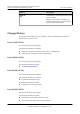
Huawei AP3x10xN&5x10xN&5x30xN&6x10xN&7x10xN Hardware Installation and Maintenance Guide Symbol About This Document Description Calls attention to important information, best practices and tips. NOTE NOTE is used to address information not related to personal injury, equipment damage, and environment deterioration. Change History Changes between document issues are cumulative. The latest document issue contains all changes made in previous issues.
Huawei AP3x10xN&5x10xN&5x30xN&6x10xN&7x10xN Hardware Installation and Maintenance Guide About This Document Issue 07 (2014-01-15) This version has the following updates: Optimized the manual.
Huawei AP3x10xN&5x10xN&5x30xN&6x10xN&7x10xN Hardware Installation and Maintenance Guide Contents Contents About This Document.....................................................................................................................ii 1 Indoor AP Overview.....................................................................................................................1 1.1 Device Structure..........................................................................................................
Huawei AP3x10xN&5x10xN&5x30xN&6x10xN&7x10xN Hardware Installation and Maintenance Guide Contents 5.1.1 Cable Assembly Precautions.....................................................................................................................................38 5.1.2 Assembling Power Cables.........................................................................................................................................39 5.1.3 Assembling Ethernet Cables............................................
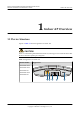
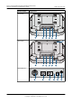
Huawei AP3x10xN&5x10xN&5x30xN&6x10xN&7x10xN Hardware Installation and Maintenance Guide 1 1 Indoor AP Overview Indoor AP Overview 1.1 Device Structure Figures in Table 1-1 show the appearance of indoor APs. CAUTION There is a scald warning label attached on the device, warning you not to touch the device after the device has been operating for a long time.
Huawei AP3x10xN&5x10xN&5x30xN&6x10xN&7x10xN Hardware Installation and Maintenance Guide Product Model 1 Indoor AP Overview Appearance AP5030DN 2 Console GE1 6 4 GE0/PoE 5 DC 12V 1 7 AP5130DN 10 2 Console GE1 GE0/PoE DC 12V 6 4 5 1 7 AP6310SN-GN 2.4G 8 Issue 11 (2015-05-18) Console 6 Huawei Proprietary and Confidential Copyright © Huawei Technologies Co., Ltd.
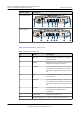
Huawei AP3x10xN&5x10xN&5x30xN&6x10xN&7x10xN Hardware Installation and Maintenance Guide Product Model 1 Indoor AP Overview Appearance AP7110DN-AGN 9 Console ETH/PoE 6 3 11 Default DC 12V 2 1 7 8 7 8 AP7110SN-GN Console 11 6 ETH/PoE Default 3 DC 12V 2 1 Table 1-2 describes interfaces on indoor APs. Table 1-2 Interfaces on indoor APs Issue 11 (2015-05-18) No. Name Description 1 DC 12 V DC power socket: connects a 12 V power adapter to the AP.
Huawei AP3x10xN&5x10xN&5x30xN&6x10xN&7x10xN Hardware Installation and Maintenance Guide 1 Indoor AP Overview No. Name Description 9 5 GHz antenna port Connects a 5 GHz antenna to the AP. 10 Dual-band antenna port Connects a dual-band antenna to the AP. 11 Device ground screw Connects a ground cable to the AP. 1.2 Indicator Description Indoor AP series products provide a single indicator or multiple indicators.
Huawei AP3x10xN&5x10xN&5x30xN&6x10xN&7x10xN Hardware Installation and Maintenance Guide 1 Indoor AP Overview Type Color Status Description Alarm Green Blinking once every 0.25s (4 Hz) l The software is being upgraded. l After the software is uploaded and started, the AP working in Fit AP mode requests to go online on the AC and maintains this state until it goes online successfully on the AC (before the CAPWAP link is established).
Huawei AP3x10xN&5x10xN&5x30xN&6x10xN&7x10xN Hardware Installation and Maintenance Guide 1 Indoor AP Overview Color Status Description Green Blinking The AP has STAs connected to the 2.4 GHz radio and is transmitting data. The indicator blinks more quickly when more data is being transmitted. Yellow Blinking The AP has STAs connected to the 5 GHz radio and is transmitting data. The indicator blinks more quickly when more data is being transmitted.
Huawei AP3x10xN&5x10xN&5x30xN&6x10xN&7x10xN Hardware Installation and Maintenance Guide 1 Indoor AP Overview NOTE When the WDS/mesh function is enabled on an AP, the blinking frequency of its Wireless LED indicates the receive signal strength on the WDS/mesh connection by default. After you connect an AP to a WDS/ mesh network, you can run the wifi-light { signal-strength | traffic } command on the AC to make the Wireless LED blinking frequency indicate receive signal strength or service traffic rate.
Huawei AP3x10xN&5x10xN&5x30xN&6x10xN&7x10xN Hardware Installation and Maintenance Guide Item 1 Indoor AP Overview Description Maximum power consumption l AP3010DN-AGN: 9.5 W l AP5010DN-AGN: 9.5 W l AP5010SN-GN: 6.0 W l AP6010DN-AGN: 10.2 W l AP6010SN-GN: 6.5 W NOTE The actual maximum power consumption depends on local laws and regulations.
Huawei AP3x10xN&5x10xN&5x30xN&6x10xN&7x10xN Hardware Installation and Maintenance Guide Item 1 Indoor AP Overview Description Operating humidity 5% to 95% (non-condensing) IP grade IP41 Atmospheric pressure 70 kPa to 106 kPa Table 1-9 Basic specifications of the AP6310SN-GN Item Description Technical specifications Dimensions (H x W x D) 35 mm x 150 mm x 130 mm Weight 0.
Huawei AP3x10xN&5x10xN&5x30xN&6x10xN&7x10xN Hardware Installation and Maintenance Guide 1 Indoor AP Overview Table 1-10 Basic specifications of the AP7110SN-GN and AP7110DN-AGN Item Description Technical specifications Dimensions (H x W x D) 45 mm x 200 mm x 200 mm Weight 1.0 kg System memory l 256 MB DDR3 l 32 MB flash memory Power specifications Power input l DC 12 V ± 10% l PoE power: -48 V DC – AP7110SN-GN: IEEE 802.3af/at – AP7110DN-AGN: IEEE 802.
Huawei AP3x10xN&5x10xN&5x30xN&6x10xN&7x10xN Hardware Installation and Maintenance Guide Part Number Issue 11 (2015-05-18) 1 Indoor AP Overview Description 2355547 Assembling Components,AP5010DN-AGN,AP5010DN-AGN Mainframe (11n,General AP Indoor,2x2 Double Frequency,Built-in Antenna,No AC/ DC adapter) 2355674 Assembling Components,AP5010SN-GN,AP5010SN-GN Mainframe (11n,General AP Indoor,2x2 Single Frequency,Built-in Antenna,No AC/DC adapter) 2356281 Assembling Components,AP5010DN-AGN-USA,AP5010DN-AG
Huawei AP3x10xN&5x10xN&5x30xN&6x10xN&7x10xN Hardware Installation and Maintenance Guide Part Number Issue 11 (2015-05-18) 1 Indoor AP Overview Description 2358563 Assembling Components,AP5130DN-FAT-DC,AP5130DN Bundle(FAT AP,11ac,General AP Indoor,3x3 Double Frequency,External Antenna,AC/ DC adapter) 2354196 Assembling Components,AP6010DN-AGN,AP6010DN-AGN Mainframe (11n,General AP Indoor,2x2 Double Frequency,Built-in Antenna,No AC/ DC adapter) 2354197 Assembling Components,AP6010SN-GN,AP6010SN-GN M
Huawei AP3x10xN&5x10xN&5x30xN&6x10xN&7x10xN Hardware Installation and Maintenance Guide Part Number Issue 11 (2015-05-18) 1 Indoor AP Overview Description 02350CVQ Assembling Components,AP7110DN-AGN-FAT-DC,AP7110DN-AGN Bundle(FAT AP,11n,Enhanced AP Indoor,3x3 Double Frequency,External Antenna,AC/DC adapter) 2356279 Assembling Components,AP7110DN-AGN-USA,AP7110DN-AGN Bundle(11n,Enhanced AP Indoor,3x3 Double Frequency,External Antenna,AC/DC adapter(US),United States dedicated) 2358266 Assembling Com
Huawei AP3x10xN&5x10xN&5x30xN&6x10xN&7x10xN Hardware Installation and Maintenance Guide 2 AP Installation 2 AP Installation 2.1 Preparing for Installation This section describes safety precautions and tool preparations for AP installation. Safety Precautions l Take proper measures to prevent injuries and device damage. l Place the device in a dry and flat position away from any liquid and prevent the device from slipping. l Keep the device clean. l Do not put the device and tools in the aisles.
Huawei AP3x10xN&5x10xN&5x30xN&6x10xN&7x10xN Hardware Installation and Maintenance Guide 2 AP Installation Hammer drill (φ6) Utility knife Cable cutter Diagonal pliers RJ45 crimping tool Wire stripper Network cable tester Multimeter Inner hexagon wrench Ladder Adjustable wrench Rubber mallet ESD gloves Level 2.2 Installation Flowchart The following figure shows the process for installing an indoor AP.
Huawei AP3x10xN&5x10xN&5x30xN&6x10xN&7x10xN Hardware Installation and Maintenance Guide 2 AP Installation Figure 2-1 Installation flowchart of the AP3010DN-AGN, AP5010DN-AGN, AP5010SN-GN, AP6010DN-AGN, AP6010SN-GN, AP6310SN-GN, AP7110SN-GN and AP7110DN-AGN Start Check before installation To a T-rail Fix the wall-mounting bracket to a T-rail Determine the installation location Against the ceiling Against the wall Fix the wall-mounting Fix the wall-mounting bracket against the wall bracket against the
Huawei AP3x10xN&5x10xN&5x30xN&6x10xN&7x10xN Hardware Installation and Maintenance Guide 2 AP Installation Figure 2-2 Installation flowchart of the AP5030DN and AP5130DN Start Check before installation Determine the installation location To a T-rail Fix the wall-mounting bracket to a T-rail Against the ceiling Connect the cable Against the wall Fix the wall-mounting Fix the wall-mounting bracket against the wall bracket against the ceiling Install the AP Connect the security lock to the lock hole Chec
Huawei AP3x10xN&5x10xN&5x30xN&6x10xN&7x10xN Hardware Installation and Maintenance Guide 2 AP Installation No. Item Quantity 3 Sheet metal mounting bracket4 1 4 2.4 GHz antenna1 3 5 5 GHz antenna1 3 6 Dual-band antenna port2 3 7 Expansion screws 3 8 OT terminal3 2 9 Quick Start Guide 1 Pay attention to the following: 1. Three 2.4 GHz antennas and three 5 GHz antennas are contained in the AP7110DN-AGN carton, and three 2.4 GHz antennas are contained in the AP7110SN-GN carton.
Huawei AP3x10xN&5x10xN&5x30xN&6x10xN&7x10xN Hardware Installation and Maintenance Guide 2 AP Installation l Install the AP away from electronic devices that can cause radio interference, such as the microwave oven. l Install the AP in a hidden position that does not affect daily lives and work of residents. l Install the AP in a site that is free from leaking or dripping water, heavy dew, and humidity, and take protective measures to prevent water from flowing into the equipment along the cable.
Huawei AP3x10xN&5x10xN&5x30xN&6x10xN&7x10xN Hardware Installation and Maintenance Guide 2 AP Installation Figure 2-5 Cable deployment and AP installation NOTE l The AP5030DN and AP5130DN must have cables connected first before installation. Except the two models, the procedures for installing the other models of indoor APs are the same unless otherwise stated. The following figures use the AP7110DN-AGN as an example. l If the AP surface is covered with protective film, remove it before installation. 2.
Huawei AP3x10xN&5x10xN&5x30xN&6x10xN&7x10xN Hardware Installation and Maintenance Guide 2 AP Installation 1 2 25mm~30mm 3. Fix the mounting bracket to the wall and use the Phillips screwdriver to fasten three expansion screws into the expansion tubes. UP UP ST3.5 0.3N•m 4. Issue 11 (2015-05-18) Align the mounting holes at the rear of the AP with the mounting screws on the mounting bracket and hang the AP on the bracket. Press the AP downwards to secure the AP on the wall.
Huawei AP3x10xN&5x10xN&5x30xN&6x10xN&7x10xN Hardware Installation and Maintenance Guide 2 AP Installation 5G 1 2 LAB 5G 5G EL NOTE The AP5030DN and AP5130DN use a different type of sheet metal mounting bracket than other APs. When installing an AP5030DN or AP5130DN, align the mounting screws at the rear of the AP with the mounting holes on the sheet metal mounting bracket and then press the AP downwards to secure the AP on the bracket. 2.5.2 Ceiling Mounting 1.
Huawei AP3x10xN&5x10xN&5x30xN&6x10xN&7x10xN Hardware Installation and Maintenance Guide 2 AP Installation 1 UP 2 UP 35mm 3 1. Ceiling tile 2. Adjustable buckle 3. M4x30 screw NOTICE The screws provided for ceiling-mounting of APs are 30 mm long and can be used to fix an AP on a ceiling not thicker than 15 mm. To install APs on thicker ceilings, you need to purchase longer screws.
Huawei AP3x10xN&5x10xN&5x30xN&6x10xN&7x10xN Hardware Installation and Maintenance Guide 2 AP Installation NOTE Only the AP6310SN-GN and AP7110 series require the locking clip during their installation. 2. Remove two ceiling tiles around the T-rail, use screws to fix the adjustable buckle to the mounting bracket, hook the adjustable buckle to the T-rail, and secure the screw on the adjustable buckle to fasten the mounting bracket and T-rail. 1 2 3 1. T-rail 3.
Huawei AP3x10xN&5x10xN&5x30xN&6x10xN&7x10xN Hardware Installation and Maintenance Guide 2 AP Installation Figure 2-6 Removing an AP 1 metal sheet 2 SYS Link Wireless 5G 5G 5G 2.6 Connecting Cables Figures in Table 2-3 show the appearance of indoor APs.
Huawei AP3x10xN&5x10xN&5x30xN&6x10xN&7x10xN Hardware Installation and Maintenance Guide Product Model 2 AP Installation Appearance AP5030DN Console GE1 GE0/PoE 5 DC 12V 6 AP5130DN 3 Console GE1 GE0/PoE 5 DC 12V 6 AP6310SN-GN 2.4G Console 2 Issue 11 (2015-05-18) Huawei Proprietary and Confidential Copyright © Huawei Technologies Co., Ltd.
Huawei AP3x10xN&5x10xN&5x30xN&6x10xN&7x10xN Hardware Installation and Maintenance Guide Product Model 2 AP Installation Appearance AP7110DN-AGN Console 1 ETH/PoE 4 Default 5 DC 12V 6 2 AP7110SN-GN Console 4 ETH/PoE Default 5 DC 12V 6 2 Table 2-4 describes cable connections of indoor APs. Table 2-4 Cable connections of indoor APs No. Cable Description 1 5 GHz antenna cable Connects a 5 GHz antenna to the AP to send and receive service signals. 2 2.
Huawei AP3x10xN&5x10xN&5x30xN&6x10xN&7x10xN Hardware Installation and Maintenance Guide 2 AP Installation No. Cable Description 6 DC power adapter l The AP supports the PoE power supply and DC power supply. l To connect the AP to a DC power source, use the power adapter delivered with the AP; otherwise, the AP maybe damaged. NOTE l Different power adapters are delivered with indoor AP products according to standards in the countries or regions where the AP products are delivered.
Huawei AP3x10xN&5x10xN&5x30xN&6x10xN&7x10xN Hardware Installation and Maintenance Guide 2 AP Installation l Before removing network cables or power cables from an AP5030DN or AP5130DN, remove the AP from the mounting bracket first to prevent damage to the network cables or power cables. l The cable cannot exceed 100 meters. 2.7 Installing the Security Lock There is a security slot on the AP. You can lock the AP to an immovable object to prevent the AP against theft.
Huawei AP3x10xN&5x10xN&5x30xN&6x10xN&7x10xN Hardware Installation and Maintenance Guide 2 AP Installation No. Check Item 7 The working ground, protection ground, and surge protection ground share the same group of ground bars. 8 Connectors of signal cables are complete, intact, and tightly connected. The signal cables are not damaged or broken. 9 Labels on cables, feeders, or jumpers are clear and correct. 2.9 Powering on the AP Indoor APs support the DC power supply and PoE power supply.
Huawei AP3x10xN&5x10xN&5x30xN&6x10xN&7x10xN Hardware Installation and Maintenance Guide 3 3 Logging In to the AP Logging In to the AP 3.1 Logging In to the AP Through the Console Port This section describes how to log in to the AP through the console port. After logging in to the AP, you can configure the AP using commands. 1. Connect a PC to the AP using a console cable. Connect the RJ45 connector to the console port of the AP and the DB9 connector to the serial port of a PC.
Huawei AP3x10xN&5x10xN&5x30xN&6x10xN&7x10xN Hardware Installation and Maintenance Guide l 3 Logging In to the AP Configuring the PC's IP address and subnet mask. The IP address must be on the network segment 169.254.0.0/16 but cannot be 169.254.1.1. 169.254.1.100 is recommended. The subnet mask is 255.255.0.0. NOTE l Ensuring that the IP address 169.254.1.1 and subnet mask 255.255.0.0 have been configured on VLANIF 1 of the device before the delivery, and GE0/0/0 has been added to VLAN 1 by default.
Huawei AP3x10xN&5x10xN&5x30xN&6x10xN&7x10xN Hardware Installation and Maintenance Guide 3. 3 Logging In to the AP Click Open. Enter the user name and password at the prompt, and press Enter. You have logged in to the device. (The following information is only for reference.) login as: admin Sent username "admin" admin@169.254.1.1's password: NOTE It is recommended that you change the initial user name and password after login. 3.
Huawei AP3x10xN&5x10xN&5x30xN&6x10xN&7x10xN Hardware Installation and Maintenance Guide 3 Logging In to the AP NOTE You can run the quit command to exit from the Telnet window. When the system fails to exit from the Telnet window: l If you logged in to the AP from an AC or a switch, press Ctrl+T to return to the AC or switch view. This operation does not affect AP services. l If you logged in to the AP from a PC, directly close the Telnet window. This operation does not affect AP services. 3.
Huawei AP3x10xN&5x10xN&5x30xN&6x10xN&7x10xN Hardware Installation and Maintenance Guide 4 Hardware Failures 4 Hardware Failures 4.1 A Device Fails to Be Powered On Fault Description The SYS indicator of a device is off. Possible Causes Power Supply Mode Possible Cause Power supply using a power module l The power switch on the device is turned off. l The power cable is not securely connected to the device. l The power supply unit has failed.
Huawei AP3x10xN&5x10xN&5x30xN&6x10xN&7x10xN Hardware Installation and Maintenance Guide 4 Hardware Failures Troubleshooting Procedure Power Supply Mode Troubleshooting Procedure Power supply using a power module 1. Check that the power switch is on. 2. Check that the power cable is securely connected to the device. 3. Check whether the power supply is normal. Replace the power adapter with a normal one. If the device is powered on, the original power adapter is faulty.
Huawei AP3x10xN&5x10xN&5x30xN&6x10xN&7x10xN Hardware Installation and Maintenance Guide 4 Hardware Failures Troubleshooting Procedure 1. Replace the optical fiber and optical module and check whether the optical interface can turn Up. Ensure that the optical module meets the following requirements. 2. Determine optical module attributes. l The optical module has passed Huawei certification. l The transmission speed of the optical module is the same as the interface speed.
Huawei AP3x10xN&5x10xN&5x30xN&6x10xN&7x10xN Hardware Installation and Maintenance Guide 5 Appendix 5 Appendix 5.1 On-site Cable Assembly and Installation 5.1.1 Cable Assembly Precautions Checking the Appearance of Cables l If the cable jacket or insulation is visibly dirty, clean it before assembly. l If the jacket or insulation of a cable has visible damage, irreparable scuffing, or other defects, do not use the cable. l If the shield layer of a cable is damaged, do not use the cable.
Huawei AP3x10xN&5x10xN&5x30xN&6x10xN&7x10xN Hardware Installation and Maintenance Guide 5 Appendix – Coil cables longer than 2 m (6.56 ft) after cutting. Bind and fasten the coils using bundling ropes. The inner diameters of the coils should be larger than 20 times the outer diameters of the cables. – When stripping the jackets of cables, avoid damaging the shield layers (braid or aluminum foil), insulation, core conductors, and other jackets that do not need to be stripped.
Huawei AP3x10xN&5x10xN&5x30xN&6x10xN&7x10xN Hardware Installation and Maintenance Guide 5 Appendix Procedure Step 1 Based on the cross-sectional area of the cable conductor, strip a length of insulation coating C to expose the conductor D of length L1, as shown in Figure 5-2. The recommended values of L1 are listed in Table 5-1. Figure 5-2 Stripping a power cable (OT terminal) NOTICE l When you strip a power cable, do not damage the conductor of the cable.
Huawei AP3x10xN&5x10xN&5x30xN&6x10xN&7x10xN Hardware Installation and Maintenance Guide 5 Appendix NOTE If you are proficient in assembling OT terminals and power cables, you can obtain the value of L1 by comparing the part to be crimped with the power cable. Step 2 Put the heat-shrinkable (A) tubing onto the bare crimping terminal, as shown in Figure 5-3.
Huawei AP3x10xN&5x10xN&5x30xN&6x10xN&7x10xN Hardware Installation and Maintenance Guide 5 Appendix Figure 5-4 Crimping the joint parts of the bare crimping terminal and the conductor (OT terminal) Step 5 Push the heat shrink tubing (A) towards the connector until the tube covers the crimped part, and then heat the tube by using a heat gun, as shown in Figure 5-5.
Huawei AP3x10xN&5x10xN&5x30xN&6x10xN&7x10xN Hardware Installation and Maintenance Guide 5 Appendix Context Figure 5-6 shows the components of a JG terminal and a power cable. Figure 5-6 Components of a JG terminal and a power cable A. JG terminal B. Heat-shrinkable tube C. Insulation layer of a power cable D. Conductor of a power cable Procedure Step 1 Based on the cross-sectional area of the cable conductor, strip a part of the cable. The L-long conductor is exposed, as shown in Figure 5-7.
Huawei AP3x10xN&5x10xN&5x30xN&6x10xN&7x10xN Hardware Installation and Maintenance Guide 5 Appendix Table 5-2 Mapping between the cross-sectional area of the conductor and the value of L Cross-Sectional Area of Conductor (mm2(in.2)) Value of L (mm(in.)) 16 (0.025) 13 (0.51) 25 (0.039) 14 (0.55) 35 (0.054) 16 (0.63) 50 (0.077) 16 (0.63) Step 2 Put the heat shrink tubing onto the bare crimping terminal, as shown in Figure 5-8.
Huawei AP3x10xN&5x10xN&5x30xN&6x10xN&7x10xN Hardware Installation and Maintenance Guide 5 Appendix Figure 5-10 Heating the heat shrink tubing (JG terminal) ----End Assembling the Cord End Terminal and the Power Cable Context Figure 5-11 shows the components of a cord end terminal and a power cable. Figure 5-11 Components of a cord end terminal and a power cable A. Cord end terminal B. Insulation layer of a power cable C.
Huawei AP3x10xN&5x10xN&5x30xN&6x10xN&7x10xN Hardware Installation and Maintenance Guide 5 Appendix NOTICE When you strip a power cable, do not damage the conductor of the cable. Figure 5-12 Stripping a power cable (cord end terminal) Table 5-3 Mapping between the cross-sectional area of the conductor and the value of L1 CrossSectional Area of Conductor (mm2(in.2)) Value of L1 (mm (in.)) Cross-Sectional Area of Conductor (mm2(in.2)) Value of L1 (mm (in.)) 1 (0.002) 8 (0.31) 10 (0.015) 15 (0.
Huawei AP3x10xN&5x10xN&5x30xN&6x10xN&7x10xN Hardware Installation and Maintenance Guide 5 Appendix Figure 5-13 Put the cord end terminal onto the conductor Step 3 Crimp the joint parts of the cord end terminal and the conductor, as shown in Figure 5-14. Figure 5-14 Crimping the cord end terminal and the conductor Step 4 Check the maximum width of the tubular crimped terminal. The maximum width of a tubular crimped terminal is listed in Table 5-4.
Huawei AP3x10xN&5x10xN&5x30xN&6x10xN&7x10xN Hardware Installation and Maintenance Guide 5 Appendix Cross-Sectional Area of Tubular Terminal (mm2(in.2)) Maximum Width of Crimped Terminal W1 (mm(in.)) 6 (0.009) 4 (0.16) 10 (0.015) 5.3 (0.21) 16 (0.025) 6 (0.24) 25 (0.039) 8.7 (0.34) 35 (0.054) 10 (0.39) ----End 5.1.3 Assembling Ethernet Cables Assembling the Shielded RJ45 Connector and Ethernet Cable Context Figure 5-15 shows the components of an RJ45 connector and a shielded Ethernet cable.
Huawei AP3x10xN&5x10xN&5x30xN&6x10xN&7x10xN Hardware Installation and Maintenance Guide 5 Appendix Figure 5-16 Fit the jacket of the connector onto the Ethernet cable Step 2 Remove a 30 mm (1.18 in.) long section of the jacket, cut off the nylon twine inside the jacket, and cut a no more than 5 mm (0.20 in.) cleft in the jacket, as shown in Figure 5-17. NOTICE l When you remove a section of the jacket, do not damage the shield layer of the twisted-pair cable.
Huawei AP3x10xN&5x10xN&5x30xN&6x10xN&7x10xN Hardware Installation and Maintenance Guide 5 Appendix Figure 5-18 Fitting the metal shell onto the twisted-pair cable Step 4 Fit the metal shell onto the twisted-pair cable until the shield layer is covered completely. Along the edge of the metal shell, cut off the aluminum foil shield layer and ensure that there is no surplus copper wire. The exposed twisted-pair cable is about 20 mm (0.79 in.) long, as shown in Figure 5-19.
Huawei AP3x10xN&5x10xN&5x30xN&6x10xN&7x10xN Hardware Installation and Maintenance Guide 5 Appendix Figure 5-21 Cable locations in a wire holder White-Orange Orange White-Green Green Blue White-Blue White-Brown Brown Step 6 Align the four pairs of cables in the holder, as shown in Figure 5-22. The connections between the wires and the pins are shown in Figure 5-23 and listed in Table 5-5.
Huawei AP3x10xN&5x10xN&5x30xN&6x10xN&7x10xN Hardware Installation and Maintenance Guide 5 Appendix Figure 5-23 Connections between wires and pins White-Orange Orange White-Green Blue White-Blue Green White-Brown Brown Pin 8 Pin 1 Table 5-5 Connections between wires and pins (using a straight-through cable as an example) Matching Pins of Wires Wire Color 1 White-Orange 2 Orange 3 White-Green 4 Blue 5 White-Blue 6 Green 7 White-Brown 8 Brown Step 7 Cut off the surplus cables along the lo
Huawei AP3x10xN&5x10xN&5x30xN&6x10xN&7x10xN Hardware Installation and Maintenance Guide 5 Appendix Figure 5-24 Cutting off surplus cables Step 8 Put the connector body onto the wire holder and turn the metal shell by 90°, as shown in Figure 5-25. NOTE Ensure that the wire holder is in good contact with the connector body. Figure 5-25 Put the connector body onto the wire holder Step 9 Push the metal shell towards the connector body until the wire holder and the connector body are engaged completely.
Huawei AP3x10xN&5x10xN&5x30xN&6x10xN&7x10xN Hardware Installation and Maintenance Guide 5 Appendix Step 10 Push the jacket towards the metal shell until the metal shell is covered. This completes the assembly of one end of the cable, as shown in Figure 5-27. Figure 5-27 Pushing the metal shell Step 11 To complete the assembly of the other end, repeat Step 1 through Step 10.
Huawei AP3x10xN&5x10xN&5x30xN&6x10xN&7x10xN Hardware Installation and Maintenance Guide 5 Appendix Procedure Step 1 Remove a 16-mm (0.63 in.) long section of the jacket, as shown in Figure 5-29. NOTICE When you remove the shield layer, do not damage the insulation of the twisted-pair cable. Figure 5-29 Removing the jacket of a twisted-pair cable (unit: mm (in.)) Step 2 Align the four pairs of wires and cut the ends neatly, as shown in Figure 5-30.
Huawei AP3x10xN&5x10xN&5x30xN&6x10xN&7x10xN Hardware Installation and Maintenance Guide 5 Appendix Matching Pins of Wires Wire Color 8 Brown Step 3 Feed the cable into the plug, and crimp the connector, as shown in Figure 5-31. NOTE When inserting the cable, check from the side or bore of the plug to ensure that the cable is completely seated in the plug. Figure 5-31 Crimping the connector Step 4 To complete the assembly of the other end, repeat Step 1 through Step 3.
Huawei AP3x10xN&5x10xN&5x30xN&6x10xN&7x10xN Hardware Installation and Maintenance Guide 5 Appendix NOTE All unqualified pieces must be crimped again. Figure 5-32 Contact strips of different heights Figure 5-33 Contact strips of the same height Step 2 Hold an RJ45 connector and turn it 45°. Observe the top edges of the metal contact strips. Figure 5-34 shows an unqualified piece.
Huawei AP3x10xN&5x10xN&5x30xN&6x10xN&7x10xN Hardware Installation and Maintenance Guide 5 Appendix Step 3 Check whether the contact strips are clean. If they are not clean and the dirt cannot be removed, replace it with a new RJ45 connector. Figure 5-35 shows an unqualified piece. Figure 5-35 Dirt on a contract strip Step 4 Check whether the contact strips and the plastic separators are well aligned and intact. If a separator is skew and cannot be fixed, replace it with a new RJ45 connector.
Huawei AP3x10xN&5x10xN&5x30xN&6x10xN&7x10xN Hardware Installation and Maintenance Guide 5 Appendix ----End Testing the Connection of Assembled Cables Context Huawei provides two types of Ethernet cables: straight-through cables and crossover cables. l Straight-through cables are connected in a one-to-one manner. They are used to connect terminals such as a computer or switch to network devices. Table 5-7 lists the connections of core wires in a straight-through cable.
Huawei AP3x10xN&5x10xN&5x30xN&6x10xN&7x10xN Hardware Installation and Maintenance Guide 5 Appendix RJ45 Connector 1 RJ45 Connector 2 Core Wire Color 7 7 Brown-White Twisted or Not Figure 5-38 shows the pins of an RJ45 connector. Figure 5-38 Pins of an RJ45 connector Pin8 Pin1 Procedure Step 1 Feed both connectors of the cable into the ports of the cable tester. Step 2 After the connectors are properly inserted, turn on the tester.
Huawei AP3x10xN&5x10xN&5x30xN&6x10xN&7x10xN Hardware Installation and Maintenance Guide 5 Appendix Step 3 Gently shake the connector and repeat Step 2 to check whether the metal contact strips are in good contact with the core wires and Ethernet ports, as shown in Figure 5-40. Figure 5-40 Checking the reliability The procedure for testing a crossover cable is the same as that for testing a straight-through cable except for the sequence in which the indicators turn on.
Huawei AP3x10xN&5x10xN&5x30xN&6x10xN&7x10xN Hardware Installation and Maintenance Guide 5 Appendix ----End 5.1.4 Installing Cable Accessories Precautions for Installing Cable Accessories Tools NOTE The illustrations in this document may differ from actual situations, but the installation methods remain the same. For example, in this document, the adapters of cable connectors have separate interfaces. In the actual situation, the adapters may have interfaces fixed on equipment.
Huawei AP3x10xN&5x10xN&5x30xN&6x10xN&7x10xN Hardware Installation and Maintenance Guide 5 Appendix l When removing densely aligned cables or fiber connectors, use dedicated pliers such as cable-pulling pliers and fiber-pulling pliers. l Do not twist, bend, stretch, or extrude fibers during installation. l Cover the fiber connectors that are not in use by using dustproof caps. Remove the dustproof caps before using the fiber connectors.
Huawei AP3x10xN&5x10xN&5x30xN&6x10xN&7x10xN Hardware Installation and Maintenance Guide 5 Appendix Figure 5-43 Installing an OT terminal, showing the orientation of crimping sleeve 2. Place the spring washer and flat washer in turn, mount a matching screw, and fasten it clockwise, as shown in Figure 5-44. Figure 5-44 Installing two terminals back to back NOTICE Ensure that the OT terminal is not in contact with other terminals or metal components. 3.
Huawei AP3x10xN&5x10xN&5x30xN&6x10xN&7x10xN Hardware Installation and Maintenance Guide 5 Appendix Figure 5-45 Installed OT terminal l Install two OT terminals on a post. Before you install two OT terminals on a post, ensure that the two terminals can be installed on the post and that the electrical connecting pieces have a large contact area. Two OT terminals can be installed using any of these methods: – Bend the upper OT terminal at a 45- or 90-degree angle, as shown in Figure 5-46.
Huawei AP3x10xN&5x10xN&5x30xN&6x10xN&7x10xN Hardware Installation and Maintenance Guide 5 Appendix NOTICE If the two terminals are different in size, place the smaller one above the bigger one. A maximum of two terminals can be installed on a post. l To remove an OT terminal, loosen the screw in the counterclockwise direction. ----End Installing the Cord End Terminal Procedure Step 1 Hold a cord end terminal upright and place it on a terminal jack, as shown in Figure 5-48.
Huawei AP3x10xN&5x10xN&5x30xN&6x10xN&7x10xN Hardware Installation and Maintenance Guide 5 Appendix NOTICE l Ensure that the exposed section of the terminal should be less than 2 mm (0.079 in.) in length. l Do not press the insulation of the terminal. l Insert only one terminal into one jack. Step 3 Move the cable slightly and ensure that it is securely connected. Step 4 Before you remove a cord end terminal, loosen the screw in the counterclockwise direction.
Huawei AP3x10xN&5x10xN&5x30xN&6x10xN&7x10xN Hardware Installation and Maintenance Guide 5 Appendix Figure 5-51 Feeding the male shielded connector into the female shielded connector Step 3 When you hear a click, the cable connector is completely inserted in the port. (The clip on the cable connector pops up to fix the connector in the port.) Pull the connector slightly and ensure that it is securely connected, as shown in Figure 5-52.
Huawei AP3x10xN&5x10xN&5x30xN&6x10xN&7x10xN Hardware Installation and Maintenance Guide 5 Appendix ----End Installing an Unshielded Ethernet Connector Procedure Step 1 Hold the male and female connectors, with the male connector facing the female connector, as shown in Figure 5-54. Figure 5-54 Holding the male and female unshielded connectors Step 2 Feed the male connector into the female connector, as shown in Figure 5-55.
Huawei AP3x10xN&5x10xN&5x30xN&6x10xN&7x10xN Hardware Installation and Maintenance Guide 5 Appendix Figure 5-56 Installed unshielded Ethernet connector Step 4 To remove an Ethernet connector, press the locking key and pull out the connector, as shown in Figure 5-57. Figure 5-57 Removing an unshielded Ethernet connector ----End Installing Fiber Connectors Issue 11 (2015-05-18) Huawei Proprietary and Confidential Copyright © Huawei Technologies Co., Ltd.
Huawei AP3x10xN&5x10xN&5x30xN&6x10xN&7x10xN Hardware Installation and Maintenance Guide 5 Appendix Context NOTICE l After you remove the dustproof cap, ensure that the fiber pins are clean and install them as soon as possible. l When you disassemble fiber connectors, you must use a dedicated tool if the connectors are densely installed. Cleaning Fiber Connectors Procedure Step 1 Clean the pins of a fiber connector by using lint-free cotton and alcohol.
Huawei AP3x10xN&5x10xN&5x30xN&6x10xN&7x10xN Hardware Installation and Maintenance Guide 5 Appendix Figure 5-59 Feeding the male connector into the female connector Step 4 Fasten the locking nut in the clockwise direction and ensure that the connector is securely installed, as shown in Figure 5-60. Figure 5-60 Fastening the locking nut Step 5 To disassemble an FC fiber connector, loosen the locking nut counterclockwise, and gently pull the male connector, as shown in Figure 5-61.
Huawei AP3x10xN&5x10xN&5x30xN&6x10xN&7x10xN Hardware Installation and Maintenance Guide 5 Appendix Figure 5-61 Disassembling an FC fiber connector ----End Installing an LC Fiber Connector Procedure Step 1 Remove the dustproof cap of the LC fiber connector and store it for future use. Step 2 Align the core pin of the male connector with that of the female connector, as shown in Figure 5-62.
Huawei AP3x10xN&5x10xN&5x30xN&6x10xN&7x10xN Hardware Installation and Maintenance Guide 5 Appendix Figure 5-63 Feeding the male connector into the female connector Step 4 A clicking sound indicates that the male connector is locked, as shown in Figure 5-64. Figure 5-64 Installed LC connector Step 5 To disassemble an LC fiber connector, press the locking nut to release the locking clips from the bore, and gently pull the male connector, as shown in Figure 5-65.
Huawei AP3x10xN&5x10xN&5x30xN&6x10xN&7x10xN Hardware Installation and Maintenance Guide 5 Appendix ----End Installing the SC Fiber Connector Procedure Step 1 Remove the dustproof cap of the SC fiber connector and store it for future use. Step 2 Align the core pin of the male connector with that of the female connector, as shown in Figure 5-66.
Huawei AP3x10xN&5x10xN&5x30xN&6x10xN&7x10xN Hardware Installation and Maintenance Guide 5 Appendix Step 4 To disassemble an SC fiber connector, hold the shell of the connector (do not hold the fiber) and gently pull the connector in the direction vertical to the adapter. Unlock the male connector, and then separate it from the shell, as shown in Figure 5-68.
Huawei AP3x10xN&5x10xN&5x30xN&6x10xN&7x10xN Hardware Installation and Maintenance Guide 5 Appendix Step 3 Hold the shell labeled "PUSH" and feed the male connector into the female connector until you hear a clicking sound. The male and female connectors are securely installed, as shown in Figure 5-70. Figure 5-70 Installed MPO fiber connector Step 4 To disassemble an MPO fiber connector, hold the shell labeled "PULL" and remove the male connector, as shown in Figure 5-71.
Huawei AP3x10xN&5x10xN&5x30xN&6x10xN&7x10xN Hardware Installation and Maintenance Guide 5 Appendix Figure 5-72 Loosening two fastening screws Step 2 Hold the handles of the COAX crimping tools to open the self-locking mechanism. The jaw of the COAX crimping tools opens automatically, as shown in Figure 5-73. Figure 5-73 Pliers jaw opening automatically Step 3 Remove the mould from the COAX crimping tools, as shown in Figure 5-74.
Huawei AP3x10xN&5x10xN&5x30xN&6x10xN&7x10xN Hardware Installation and Maintenance Guide 5 Appendix Figure 5-74 Removing the mould from the COAX crimping tools Step 4 Place the mould to be installed into the jaw of the COAX crimping tools and align the screw holes, as shown in Figure 5-75. Figure 5-75 Installing a new mould in the COAX crimping tools NOTICE Keep the short side of the mould inwards and the long side outwards, with the teeth of the mould aligning from the larger size to the smaller size.
Huawei AP3x10xN&5x10xN&5x30xN&6x10xN&7x10xN Hardware Installation and Maintenance Guide 5 Appendix Figure 5-76 Aligning the screw holes Step 6 Hold the handles of the COAX crimping tools with one hand. Tighten the two fastening screws in the clockwise direction. Figure 5-77 and Figure 5-78shows the mould installed in the COAX crimping tools.
Huawei AP3x10xN&5x10xN&5x30xN&6x10xN&7x10xN Hardware Installation and Maintenance Guide 5 Appendix ----End 5.2 Environmental Requirements for Device Operation 5.2.1 Environmental Requirements for an Equipment Room Requirements for Selecting a Site for an Equipment Room When designing a project, consider the communication network planning and technical requirements of the equipment. Also consider hydrographic, geological, seismic, power supply, and transportation factors.
Huawei AP3x10xN&5x10xN&5x30xN&6x10xN&7x10xN Hardware Installation and Maintenance Guide 5 Appendix corrosive gases from entering the equipment room and corroding components and circuit boards. l The room should be located far away from industrial and heating boilers. l It is recommended that the room be on or above the second floor. If this requirement cannot be met, the ground for equipment installation in the room should be at least 600 mm (23.62 in,) above the maximum flood level.
Huawei AP3x10xN&5x10xN&5x30xN&6x10xN&7x10xN Hardware Installation and Maintenance Guide 5 Appendix Construction Requirements for the Equipment Room Table 5-10 shows the construction requirements for the equipment room. Table 5-10 Construction requirements for the equipment room Issue 11 (2015-05-18) Item Requirements Area The smallest area of the equipment room can accommodate the equipment with the largest capacity.
Huawei AP3x10xN&5x10xN&5x30xN&6x10xN&7x10xN Hardware Installation and Maintenance Guide 5 Appendix Figure 5-80 Internal partition wall inside the equipment room Equipment Room Environment Dust on devices may cause electrostatic discharge and result in poor contact for connectors or metal connection points. This problem can shorten the life span of devices and cause faults. The equipment room must be free from explosive, conductive, magnetically-permeable, and corrosive dust.
Huawei AP3x10xN&5x10xN&5x30xN&6x10xN&7x10xN Hardware Installation and Maintenance Guide 5 Appendix l Use screens on the door and windows facing outside. The outer windows should be dustproof. l Clean the equipment room regularly and clean the air filter monthly. l Wear shoe covers and ESD clothes before entering the equipment room. Requirements for Corrosive Gases The room should be free from dusts and corrosive gases, such as SO2, H2S, and NH3.
Huawei AP3x10xN&5x10xN&5x30xN&6x10xN&7x10xN Hardware Installation and Maintenance Guide 5 Appendix Electromagnetism Requirements for the Equipment Room All interference sources, inside or outside the equipment room, can cause equipment problems with capacitive coupling, inductive coupling, electromagnetic wave radiation, and common impedance (including grounding system) coupling.
Huawei AP3x10xN&5x10xN&5x30xN&6x10xN&7x10xN Hardware Installation and Maintenance Guide 5 Appendix Item Requirements Grounding of DC power distribution l Connect the DC working ground (positive pole of the -48 V DC power supply or the negative pole of the 24 V DC power supply) with the indoor collective ground cable nearby. The total ground cable should meet the maximum load of the equipment.
Huawei AP3x10xN&5x10xN&5x30xN&6x10xN&7x10xN Hardware Installation and Maintenance Guide 5 Appendix Item Requirements Collective ground cable l Use the grounding ring or ground bar for the collective ground cable. l Do not use aluminum cables as ground cables. Adopt measures to prevent electrification corrosion when connecting different metal parts together. l Use the copper busbar as the collective ground cable with the crosssectional area not less than 120 mm2 (0.19 in.
Huawei AP3x10xN&5x10xN&5x30xN&6x10xN&7x10xN Hardware Installation and Maintenance Guide 5 Appendix Requirements for AC Power Supply The AC power supply consists of power mains, uninterruptable power supply (UPS), and selfsupplied electric generator. In addition to meeting the requirements of the server load, the AC power supply must have a simple connection line, safe operation, flexible scheduling, and easy maintenance.
Huawei AP3x10xN&5x10xN&5x30xN&6x10xN&7x10xN Hardware Installation and Maintenance Guide 5 Appendix l If the voltage of the power mains that supply power directly to devices exceeds the rated voltage by -10% to 5%, or exceeds the voltage range that devices can support, a voltage regulating device or voltage stabilizing device is required.
Huawei AP3x10xN&5x10xN&5x30xN&6x10xN&7x10xN Hardware Installation and Maintenance Guide 5 Appendix Item Requirements Peak noise voltage ≤200 mV Dynamic response The recovery time is less than 200 ms. The overshoot is in the range of the integral value of the DC output voltage ±5%. Recommendations for DC Power Supply The following shows recommendations for the DC power supply. l Use distributed power supply mode. Use multiple DC power supply systems and put power equipment in multiple locations.
Huawei AP3x10xN&5x10xN&5x30xN&6x10xN&7x10xN Hardware Installation and Maintenance Guide 5 Appendix No. Description 4 The ground cable must be connected securely to the protection ground bar of the equipment room. 5 Do not use other equipment as part of the ground cable or electrical connection. 5.3.2 Grounding Specifications for an Equipment Room The grounding resistance of a comprehensive communication building should be less than or equal to one ohm.
Huawei AP3x10xN&5x10xN&5x30xN&6x10xN&7x10xN Hardware Installation and Maintenance Guide 5 Appendix No. Description 6 When combining cabinets of the same type, short-circuiting cables are required to connect the ground busbars (if any) of the cabinets. The cross-sectional area of the short-circuiting cable is 6 sq. mm (0.009 sq. in.) and is no more than 300 mm (11.8 in.) long. Connect the two ends of the short-circuiting cable to the ground busbar terminals of neighboring cabinets and fix them firmly.
Huawei AP3x10xN&5x10xN&5x30xN&6x10xN&7x10xN Hardware Installation and Maintenance Guide 5 Appendix Table 5-19 Grounding specifications for signal cables No. Description 1 Equip the cable outdoors with a metal jacket, well grounded at both ends, or connect the ends of the metal jacket to the protection ground bar of the equipment room. For cables inside the equipment room, install surge protection devices at the interface to the equipment.
Huawei AP3x10xN&5x10xN&5x30xN&6x10xN&7x10xN Hardware Installation and Maintenance Guide 5 Appendix Specialized for power cables and signal cables, the types of engineering labels are as follows: l The signal cables include network cables, optical fibers, and user cables. l The power cables include the AC power cables and DC power cables. NOTE Fill in the label according to the user's requirements if the user needs an integrated description of the label.
Huawei AP3x10xN&5x10xN&5x30xN&6x10xN&7x10xN Hardware Installation and Maintenance Guide 5 Appendix Figure 5-81 Label for signal cables To specify more clearly the position of a cable, use the dividing lines on the label. For example, there is a dividing line between the cabinet number and the chassis number, and another one between the chassis number and the slot number. The dividing line is 1.5 mm x 0.6 mm (0.06 in. x 0.02 in.) with the color of Pantone 656c (light blue).
Huawei AP3x10xN&5x10xN&5x30xN&6x10xN&7x10xN Hardware Installation and Maintenance Guide 5 Appendix Figure 5-82 Power cable label Label Printing The contents can be printed or written on the labels. Printing is recommended for the sake of high efficiency and eye-pleasant layout. Template for Printing Use a template to print labels. You can obtain the template from the Huawei local office.
Huawei AP3x10xN&5x10xN&5x30xN&6x10xN&7x10xN Hardware Installation and Maintenance Guide 5 Appendix l When using the template, you can directly modify the contents of the template. The settings of centered characters, direction, and fonts should not be changed. l When there are too many characters to be filled in, zoom out the characters, but make sure that the printouts are clear and legible. Merging Cells in the Template To merge two or more cells, do as follows: 1. Select Edit/Select All. 2.
Huawei AP3x10xN&5x10xN&5x30xN&6x10xN&7x10xN Hardware Installation and Maintenance Guide 5 Appendix Requirements for Feeding the Printer The label paper consists of two layers and has undergone multiple processing procedures such as printing and cutting. No matter what model of printer you use, feed in the labels one page at a time. To avoid jamming the labels, never use the auto-feed mode. Feed in the label paper in the correct direction to ensure that the text is printed in a correct position.
Huawei AP3x10xN&5x10xN&5x30xN&6x10xN&7x10xN Hardware Installation and Maintenance Guide 5 Appendix Writing direction: The direction is shown in Figure 5-84: Figure 5-84 Writing direction of the characters on the label Attaching Labels After printing or writing the label, remove the label from the page and attach it to the signal cable, or the identification plate of the power cable. The methods for attaching labels are described in the following sections.
Huawei AP3x10xN&5x10xN&5x30xN&6x10xN&7x10xN Hardware Installation and Maintenance Guide 5 Appendix Figure 5-86 Label for signal cables Power Cable Label Remove the label from the backing page, and attach it to the identification plate on the cable tie. The label should be attached to the rectangular flute on the identification plate, and attached to only one side of the identification plate. The cable ties are bundled at 2 cm (0.79 in.
Huawei AP3x10xN&5x10xN&5x30xN&6x10xN&7x10xN Hardware Installation and Maintenance Guide 5 Appendix Figure 5-87 Binding the label for the power cable Cable TO: B03 TO: B03 -48V2 -48V2 Cable The identification card is on the top of the cable in horizontal cabling. The identification card is to the right of the cable in vertical cabling. Contents of Engineering Labels Contents of Labels for Power Cables Labels for power cables are only affixed on one side of the identification plates.
Huawei AP3x10xN&5x10xN&5x30xN&6x10xN&7x10xN Hardware Installation and Maintenance Guide 5 Appendix Therefore, the information in Area 1 at one end is the same as the information in Area 2 at the other end of the cable. In other words, the local information at one end is called the opposite information at the other end. Precautions for Using Engineering Labels When using labels, pay attention to the following points: l When printing, writing, or attaching labels, keep the labels clean.
Huawei AP3x10xN&5x10xN&5x30xN&6x10xN&7x10xN Hardware Installation and Maintenance Guide Content 5 Appendix Meaning Example D: optical interface number. Numbered in a top-bottom and left-right order, consistent with the port sequence number on the device. R: Receiving interface - T: optical transmitting interface Example of the Label Figure 5-89 shows the label on the cable.
Huawei AP3x10xN&5x10xN&5x30xN&6x10xN&7x10xN Hardware Installation and Maintenance Guide Content 5 Appendix Meaning Example B: chassis number Numbered in bottom-up order with two digits, for example, 01. C: physical slot number Numbered in the top-down and left-right order starting from 01. For example, 01 is the slot with number 1. D: optical interface number. Numbered in a top-down and left-right order, consistent with the port sequence number on the device.
Huawei AP3x10xN&5x10xN&5x30xN&6x10xN&7x10xN Hardware Installation and Maintenance Guide 5 Appendix Meaning of the label in Figure 5-90 l "ODF-G01-01-01-R" indicates that the local end of the optical fiber is connected to the optical receiving terminal on row 01, column 01 of the ODF in row G, column 01 in the machine room.
Huawei AP3x10xN&5x10xN&5x30xN&6x10xN&7x10xN Hardware Installation and Maintenance Guide 5 Appendix The contents of the labels for network cables connecting hubs and devices or agents and the network cables for other purposes should be specified according to actual connections. The details are as follows: l For a network cable connecting a hub and device, the label on the hub end should indicate the numbers of the chassis and cabinet where the hub resides, and the serial number on the hub.
Huawei AP3x10xN&5x10xN&5x30xN&6x10xN&7x10xN Hardware Installation and Maintenance Guide 5 Appendix Table 5-25 Contents of the engineering labels for user cables Content Meaning Example MN-B-C-D MN: cabinet number For example, A01 is the first cabinet in row A. B: frame number Numbered in the bottom-up order with two digits, for example, 03. C: physical slot number Numbered with two digits in the top-down and leftright order. For example, 01.
Huawei AP3x10xN&5x10xN&5x30xN&6x10xN&7x10xN Hardware Installation and Maintenance Guide 5 Appendix Engineering Labels for DC Power Cables The labels are affixed to the DC power cables that provide power supply for cabinets, including the -48 V, PGND, and BGND cables. Here, the DC power cables also include power cables and PGND cables. The labels for DC power cables are affixed to one side of the identification plates on cable ties. For details of the labels, see Table 5-26.
Huawei AP3x10xN&5x10xN&5x30xN&6x10xN&7x10xN Hardware Installation and Maintenance Guide 5 Appendix The meaning of the label in Figure 5-93 is as follows: l On the loaded cabinet side, the label "A01/B08--48V2" on the cable indicates that the cable is -48 V DC supply, which is from the eighth connector on row B of -48 V bus bar in the cabinet on row A, and column 1 in the equipment room.
Huawei AP3x10xN&5x10xN&5x30xN&6x10xN&7x10xN Hardware Installation and Maintenance Guide 5 Appendix Make sure that labels are affixed in correct direction. That is, after the cable ties are bundled onto the cable, the identification plates with the labels should face up, and the text on the labels in the same cabinet should be in the same direction, as shown in Figure 5-94.
Huawei AP3x10xN&5x10xN&5x30xN&6x10xN&7x10xN Hardware Installation and Maintenance Guide 5 Appendix Measures to Prevent Loosened Optical Module 1. When installing an optical module, insert it into position. If you hear a click or feel a slight shake, it indicates that the latch boss is secured. If the latch boss is not secured, the gold finger of the optical module is not in good contact with the connector on the board.
Huawei AP3x10xN&5x10xN&5x30xN&6x10xN&7x10xN Hardware Installation and Maintenance Guide 5 Appendix Figure 5-97 Installing a protective cap If no protective cap is available, use fibers to protect the optical module, as shown in Figure 5-98. Figure 5-98 Using fibers to protect an optical module 3. Cover unused optical connectors with protective caps, as shown in Figure 5-99, and then lay out fibers on the fiber rack or coil them in a fiber management tray to prevent fibers from being squeezed.
Huawei AP3x10xN&5x10xN&5x30xN&6x10xN&7x10xN Hardware Installation and Maintenance Guide 5 Appendix Figure 5-100 Cleaning a receptacle with a cotton swab NOTICE When cleaning a receptacle, insert the cotton swab and turn it slowly in the receptacle. Do not use too much strength because the receptacle may be damaged. 5. If optical signals are lost during the operation of a device, use the preceding method to clean the receptacle or the optical connector.
Huawei AP3x10xN&5x10xN&5x30xN&6x10xN&7x10xN Hardware Installation and Maintenance Guide BOM Code Product Description Bar Code* 5 Appendix Fault Occurring Date* Description of the Fault Phenomena* Category No.* Software Version* Reasons for Repairing (Category No.): Category No.