HUAWEI ME909 Series Mini PCIe Module Hardware Guide Issue 0.
Huawei Technologies Co., Ltd. provides customers with comprehensive technical support and service. For any assistance, please contact our local office or company headquarters. Huawei Technologies Co., Ltd. Huawei Industrial Base, Bantian, Longgang, Shenzhen 518129, People’s Republic of China Tel: +86-755-28780808 Global Hotline: +86-755-28560808 Website: www.huawei.com E-mail: mobile@huawei.com Please refer color and shape to product.
HUAWEI ME909 Series Mini PCIe Module Hardware Guide About This Document About This Document Revision History Document Version Date 0.1 2013-06-09 Chapter Descriptions Creation This is a draft version, and some chapters are still with "TBD". Issue 0.1 (2013-06-09) Huawei Proprietary and Confidential Copyright © Huawei Technologies Co., Ltd.
HUAWEI ME909 Series Mini PCIe Module Hardware Guide Contents Contents 1 Introduction.................................................................................................................................... 7 2 Overall Description ...................................................................................................................... 8 2.1 About This Chapter ...........................................................................................................................
HUAWEI ME909 Series Mini PCIe Module Hardware Guide Contents 4.5.1 Antenna Design Indicators..................................................................................................... 29 4.5.2 Interference ........................................................................................................................... 31 4.5.3 GSM/WCDMA/GPS Antenna Requirements ......................................................................... 31 4.5.4 Radio Test Environment ....................
HUAWEI ME909 Series Mini PCIe Module Hardware Guide Contents 8.13.2 FCC Statement .................................................................................................................... 55 9 Appendix A Circuit of Typical Interface ................................................................................ 56 10 Appendix B Acronyms and Abbreviations .......................................................................... 57 Issue 0.
HUAWEI ME909 Series Mini PCIe Module Hardware Guide Introduction 1 Introduction This document describes the hardware application interfaces and air interfaces provided by HUAWEI ME909 Series Mini PCIe Module, including ME909u-521, ME909u-121 and ME909u-721 (hereinafter referred to as the ME909 module). This document helps hardware engineer to understand the interface specifications, electrical features and related product information of the ME909 module.
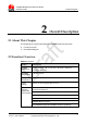
HUAWEI ME909 Series Mini PCIe Module Hardware Guide 2 Overall Description Overall Description 2.1 About This Chapter This chapter gives a general description of the ME909 module and provides: Function Overview Circuit Block Diagram 2.2 Function Overview Table 2-1 Features Feature Description Physical Dimensions Dimensions (L × W × H): 51 mm × 30.4 mm × 3.35 mm Weight: about 12 g Operating Temperature –20°C to +60°C Storage Temperature –40°C to +85°C Power Voltage DC 3.0 V–3.
HUAWEI ME909 Series Mini PCIe Module Hardware Guide Feature Overall Description Description LED_WWAN#: Active-low LED signal indicating the state of the module (the software is under development) Antenna connector WWAN MAIN antenna connector x1 WWAN AUX antenna connector x1 GPS antenna connector x1 2.3 Circuit Block Diagram Figure 2-1 shows the circuit block diagram of the ME909 Mini PCIe Adapter.
HUAWEI ME909 Series Mini PCIe Module Hardware Guide 3 Description of the Application Interfaces Description of the Application Interfaces 3.
HUAWEI ME909 Series Mini PCIe Module Hardware Guide Description of the Application Interfaces Figure 3-1 shows the sequence of pins on the interface of the Mini PCIe Adapter. Figure 3-1 Sequence of Mini-PCIe interface Table 3-1 shows the pin definitions of the Mini PCIe Interface. Table 3-1 Pin definitions of the Mini PCIe interface PIN No. Pin Name Mini PCI Express Standard Description HUAWEI Pin Description 1 WAKE# WAKE# O 2 3.
HUAWEI ME909 Series Mini PCIe Module Hardware Guide PIN No. Pin Name Mini PCI Express Standard Description HUAWEI Pin Description 8 UIM_PWR UIM_PWR P 9 GND GND 10 UIM_DATA 11 I/O Description of the Application Interfaces Description DC Characteristics (V) Min. Typ. Max. Power source for the external USIM card - 1.8/2.85 - - Ground - - - UIM_DATA I/O External USIM data signal - 1.8/2.
HUAWEI ME909 Series Mini PCIe Module Hardware Guide PIN No. Pin Name Mini PCI Express Standard Description HUAWEI Pin Description 26 GND GND - 27 GND GND 28 1.5 V 29 I/O Description of the Application Interfaces Description DC Characteristics (V) Min. Typ. Max.
HUAWEI ME909 Series Mini PCIe Module Hardware Guide PIN No. Pin Name Mini PCI Express Standard Description HUAWEI Pin Description 46 LED_WPAN# NC - 47 Reserved PCM_DOUT 48 1.5 V 49 I/O Description of the Application Interfaces Description DC Characteristics (V) Min. Typ. Max. Not connected - - - O PCM I/F data out –0.3 1.8 2.1 NC - Not connected - - - Reserved PCM_DIN I PCM I/F data in –0.3 1.8 2.
HUAWEI ME909 Series Mini PCIe Module Hardware Guide Description of the Application Interfaces 3.4 Power Supply Time Sequence Power on sequence Do not toggle RESIN_N pin during the power on sequence. Pulling RESIN_N pin low will extend time for module startup. Figure 3-2 Power on timing sequence Parameter Remarks Time (Nominal value) Unit TPD+ Power Valid to USB D+ high 14 s Power off Sequence Cutting off 3.3 V will power off the module. Figure 3-3 Power off timing sequence Issue 0.
HUAWEI ME909 Series Mini PCIe Module Hardware Guide Description of the Application Interfaces 3.5 WAKE# Signal WAKE# pin (the signal that the module uses to wake up the PC) supports software control. This signal is used for module to wake up the host. It is designed as an OC gate, so it should be pulled up by the host and it is active-low. When the module wakes up the host, the BB Chip hold 1s high-level-voltage pulse and then module output low-level-voltage to wake the host.
HUAWEI ME909 Series Mini PCIe Module Hardware Guide Description of the Application Interfaces Figure 3-5 Connections of the RESIN_N pin As the RESIN_N signal are relatively sensitive, it is recommended that you install a 10 nF to 0.1 µF capacitor near the RESIN_N pin of the interface for filtering. In addition, when you design a circuit on the PCB of the interface board, it is recommended that the circuit length should not exceed 20 mm and that the circuit should be kept at a distance of 2.
HUAWEI ME909 Series Mini PCIe Module Hardware Guide Description of the Application Interfaces 3.7 W_DISABLE# Signal The W_DISABLE# signal is provided to allow users to disable wireless communications of the module. The software version is planning. 3.8 LED_WWAN# Signal ME909 provides a LED_WWAN# signal to indicate the RF status. The ME909 module does not support this function because the software feature is under development. The planning drive strength is10 mA.
HUAWEI ME909 Series Mini PCIe Module Hardware Guide Description of the Application Interfaces Table 3-3 Definition of the USB interface Pin No. Pin Name I/O Description DC Characteristics (V) Min. Typ. Max. 36 USB_DM I/O USB signal D- - - - 38 USB_DP I/O USB signal D+ - - - According to USB protocol, for bus timing or electrical characteristics of ME909 USB signal, please refer to the chapter 7.3.2 of Universal Serial Bus Specification 2.0.
HUAWEI ME909 Series Mini PCIe Module Hardware Guide Pin No. Pin Name 8 UIM_PWR I/O P Description of the Application Interfaces Description Power source for the external USIM card DC Characteristics (V) Min. Typ. Max. - 1.8/2.85 - 3.10.2 Circuit Recommended for the USIM Card Interface As the Mini PCIe Adapter is not equipped with an USIM socket, you need to place an USIM socket on the user interface board. Figure 3-9 shows the circuit of the USIM card interface.
HUAWEI ME909 Series Mini PCIe Module Hardware Guide Description of the Application Interfaces To meet the requirements of 3GPP TS 51.010-1 protocols and electromagnetic compatibility (EMC) authentication, the USIM socket should be placed near the PCIe interface (it is recommended that the PCB circuit connects the PCIe interface and the USIM socket does not exceed 100 mm), because a long circuit may lead to wave distortion, thus affecting signal quality.
HUAWEI ME909 Series Mini PCIe Module Hardware Guide Description of the Application Interfaces Figure 3-10 Circuit diagram of the interface of the PCM (ME909 module is used as PCM master) PCM_SYNC: Output when PCM is in master mode; PCM_CLK: Output when PCM is in master mode; The PCM function of ME909 only supports master mode; It is recommended that a TVS be used on the related interface, to prevent electrostatic discharge and protect integrated circuit (IC) components. 3.
HUAWEI ME909 Series Mini PCIe Module Hardware Guide Description of the Application Interfaces Figure 3-11 RF antenna connectors AUX GPS MAIN The antenna connectors must be used with coaxial cables with characteristic impedance of 50Ω. 3.13 Reserved Pins The ME909 module provides 2 reserved pins. All of reserved pins cannot be used by the customer. Table 3-6 Reserved pins Pin No. Pin Name I/O Description 17, 19 Reserved - Reserved, please keep open. 3.
HUAWEI ME909 Series Mini PCIe Module Hardware Guide Description of the Application Interfaces Table 3-7 NC pins Pin No. Pin Name I/O Description 3, 5–7, 11, 13, 16, 23, 25, 28, 30–33, 44, 46, 48 NC - Not connected, please keep open. Issue 0.1 (2013-06-09) Huawei Proprietary and Confidential Copyright © Huawei Technologies Co., Ltd.
HUAWEI ME909 Series Mini PCIe Module Hardware Guide RF Specifications 4 RF Specifications 4.1 About This Chapter This chapter describes the RF specifications of the ME909 module, including: Operating Frequencies Conducted RF Measurement Conducted Rx Sensitivity and Tx Power Antenna Design Requirements 4.2 Operating Frequencies Table 4-1 shows the RF bands supported by the ME909u-521 module.
HUAWEI ME909 Series Mini PCIe Module Hardware Guide RF Specifications Operating Band Tx Rx LTE Band V 824 MHz–849 MHz 869 MHz–894 MHz LTE Band VIII 880 MHz–915 MHz 925 MHz–960 MHz LTE Band VII 2500 MHz–2570 MHz 2620 MHz–2690 MHz LTE Band XX 832 MHz–862 MHz 791 MHz–821 MHz GPS L1 - 1574.42 MHz–1576.42 MHz GLONASS - 1597.55 MHz–1605.89 MHz 4.3 Conducted RF Measurement 4.3.
HUAWEI ME909 Series Mini PCIe Module Hardware Guide RF Specifications The 3GPP Protocol Claim column in Table 4-2 lists the required minimum values, and the Test Value column lists the tested values of the ME909u-521 module.
HUAWEI ME909 Series Mini PCIe Module Hardware Guide RF Specifications 4.4.2 Conducted Transmit Power The conducted transmit power is another indicator that measures the performance of ME909u-521 module. The conducted transmit power refers to the maximum power that the module tested at the antenna connector can transmit. According to the 3GPP protocol, the required transmit power varies with the power class. able 4-4 lists the required ranges of the conducted transmit power of the T ME909u-521 module.
HUAWEI ME909 Series Mini PCIe Module Hardware Guide RF Specifications 4.5 Antenna Design Requirements 4.5.1 Antenna Design Indicators Antenna Efficiency Antenna efficiency is the ratio of the input power to the radiated or received power of an antenna. The radiated power of an antenna is always lower than the input power due to the following antenna losses: return loss, material loss, and coupling loss. The efficiency of an antenna relates to its electrical dimensions.
HUAWEI ME909 Series Mini PCIe Module Hardware Guide Distance between antennas Antenna type Antenna direction RF Specifications The primary antenna must be placed as near as possible to the ME909 module to minimize the cable length. The diversity antenna needs to be installed perpendicularly to the primary antenna. The diversity antenna can be placed farther away from the ME909 module. Antenna isolation can be measured with a two-port vector network analyzer.
HUAWEI ME909 Series Mini PCIe Module Hardware Guide RF Specifications Antenna direction The antenna correlation coefficient differs from the antenna isolation. Sufficient antenna isolation does not represent a satisfactory correlation coefficient. For this reason, the two indicators need to be evaluated separately. For the antennas on laptops, the recommended envelope correlation coefficient between the primary antenna and the diversity antenna is smaller than 0.5.
HUAWEI ME909 Series Mini PCIe Module Hardware Guide RF Specifications Antenna Requirements Frequency range Depending on frequency band(s) provided by the network operator, the customer must use the most suitable antenna for that/those band(s) Bandwidth of main antenna 70 MHz in GSM850 80 MHz in GSM900 170 MHz in DCS 140 MHz in PCS 250 MHz in WCDMA /LTE Band 1 140 MHz in WCDMA/LTE Band 2 70 MHz in WCDMA/LTE Band 5 80 MHz in WCDMA/LTE Band 8 170 MHz in LTE Band 3 190 MHz in LTE Band 7 71 MHz in LTE Band
HUAWEI ME909 Series Mini PCIe Module Hardware Guide RF Specifications Passive Tests Antenna efficiency Gain Pattern shape Envelope correlation coefficient TRP: GSM, WCDMA, CDMA, TD-SCDMA, and LTE systems TIS: GSM, WCDMA, CDMA, TD-SCDMA, and LTE systems Active Tests Figure 4-1 shows the SATIMO microwave testing chamber. Figure 4-1 SATIMO microwave testing chamber Issue 0.1 (2013-06-09) Huawei Proprietary and Confidential Copyright © Huawei Technologies Co., Ltd.
HUAWEI ME909 Series Mini PCIe Module Hardware Guide 5 Electrical and Reliability Features Electrical and Reliability Features 5.1 About This Chapter This chapter describes the electrical and reliability features of the interfaces in the ME909 module, including: Absolute Ratings Operating and Storage Temperatures and Humidity Electrical Features of USIM Power Supply Features Reliability Features EMC and ESD Features 5.
HUAWEI ME909 Series Mini PCIe Module Hardware Guide Electrical and Reliability Features 5.3 Operating and Storage Temperatures and Humidity able 5-2 lists the operating and storage temperatures and humidity for the ME909 T module. Table 5-2 Operating and storage temperatures and humidity for the ME909 module Specification Min. Max.
HUAWEI ME909 Series Mini PCIe Module Hardware Guide Electrical and Reliability Features Parameter Description Minimum Value Maximum Value Unit VIL Logic low-level input voltage –0.3 0.35 x VDD_PX V VOH Logic high-level output voltage VDD_PX–0.45 VDD_PX V VOL Logic low-level output voltage 0 0.45 V 5.6 Power Supply Features 5.6.1 Input Power Supply Table 5-5 lists the requirements for input power of the ME909 module.
HUAWEI ME909 Series Mini PCIe Module Hardware Guide Electrical and Reliability Features 5.6.2 Power Consumption The power consumptions of ME909 module in different scenarios are respectively listed in Table 5-7 , Table 5-8 , Table 5-9 and Table 5-10 . The power consumption listed in this section is tested when the power supply of the ME909 module is 3.3 V. Typical values are measured at room temperature, and minimum and maximum values are measured over the entire operating temperature range.
HUAWEI ME909 Series Mini PCIe Module Hardware Guide Electrical and Reliability Features Description Bands Test Value Units Notes/Configuration HSPA+/WCDMA UMTS bands TBD mA Module is powered up and idle (Idle) DRX cycle=8 (2.56 s) Module is registered on the 3G network, and PDP is activated, No data transmission. USB is not in suspend mode. GSM/ GPRS/EDGE GSM bands TBD mA Module power up and idle MFRMS=5 (1.
HUAWEI ME909 Series Mini PCIe Module Hardware Guide Description LTE Electrical and Reliability Features Band Test Value Units (IMT2100) TBD 10 dBm Tx Power TBD 23.5 dBm Tx Power mA Band II TBD (PCS 1900) TBD 10 dBm Tx Power TBD 23.5 dBm Tx Power mA 1 dBm Tx Power Band V TBD (850 MHz) TBD 10 dBm Tx Power TBD 23.5 dBm Tx Power TBD (900 MHz) TBD 10 dBm Tx Power TBD 23.
HUAWEI ME909 Series Mini PCIe Module Hardware Guide Description Band Electrical and Reliability Features Test Value Units TBD LTE Band XX TBD Power (dBm) 23 dBm Tx Power mA 1 dBm Tx Power TBD 10 dBm Tx Power TBD 23 dBm Tx Power Table 5-9 DC power consumption of ME909u-521 (GPRS/EDGE) Description Test Value Units PCL Configuration GPRS850 TBD mA 5 1 Up/1 Down TBD 2 Up/1 Down TBD 4 Up/1 Down TBD GPRS900 TBD 4 Up/1 Down TBD mA 5 1 Up/1 Down TBD 2 Up/1 Down TBD 4 Up/1 Dow
HUAWEI ME909 Series Mini PCIe Module Hardware Guide Description Test Value Electrical and Reliability Features Units PCL TBD EDGE850 4 Up/1 Down TBD mA TBD 4 Up/1 Down mA 15 1 Up/1 Down TBD 2 Up/1 Down TBD 4 Up/1 Down TBD mA 8 1 Up/1 Down TBD 2 Up/1 Down TBD 4 Up/1 Down mA 15 1 Up/1 Down TBD 2 Up/1 Down TBD 4 Up/1 Down TBD mA 2 1 Up/1 Down TBD 2 Up/1 Down TBD 4 Up/1 Down TBD EDGE1900 1 Up/1 Down 2 Up/1 Down TBD EDGE1800 8 TBD TBD EDGE900 Configuration mA 10
HUAWEI ME909 Series Mini PCIe Module Hardware Guide Electrical and Reliability Features The above values are the average of some test samples. LTE test condition: 10 MHz bandwidth, QPSK, 1RB when testing max Tx power and full RB when testing 1 dBm or 10 dBm. 5.7 Reliability Features Table 5-11 lists the test conditions and results of the reliability of the ME909 module .
HUAWEI ME909 Series Mini PCIe Module Hardware Guide Electrical and Reliability Features Item Test Condition Sine vibration Frequency range: 5 Hz to 200 Hz Acceleration: 10 m/s Standard IEC60068 2 Frequency scan rate: 1 oct/min Test period: 3 axial directions. Five circles for each axial direction. Shock test Half-sine wave shock Peak acceleration: 300 m/s IEC60068 2 Shock duration: 11 ms Test period: 6 axial directions. One shock for each axial direction.
HUAWEI ME909 Series Mini PCIe Module Hardware Guide Electrical and Reliability Features A metallic or plastic case with conductive paint is recommended, except for the area around the antenna. The HUAWEI ME909 module does not include any protection against over voltage. Issue 0.1 (2013-06-09) Huawei Proprietary and Confidential Copyright © Huawei Technologies Co., Ltd.
HUAWEI ME909 Series Mini PCIe Module Hardware Guide 6 Mechanical Specifications Mechanical Specifications 6.1 About This Chapter This chapter mainly describes mechanical specifications of ME909 module, including: Dimensions and Interfaces Dimensions of the Mini PCI Express Connector Specification Selection for Fasteners 6.2 Dimensions and Interfaces The dimensions of the ME909 module are 51 mm (length) × 30.4 mm (width) ×3.35 mm (height).
HUAWEI ME909 Series Mini PCIe Module Hardware Guide Mechanical Specifications Figure 6-1 Dimensions of the ME909 module 6.3 Dimensions of the Mini PCI Express Connector The Mini PCIe Adapter adopts a standard Mini PCI Express connector that has 52 pins and complies with the PCI Express Mini Card Electromechanical Specification Revision 1.2. igure 6-2 shows a 52-pin Mini PCI Express connector (take the Molex 67910002 as F an example). Issue 0.
HUAWEI ME909 Series Mini PCIe Module Hardware Guide Mechanical Specifications Figure 6-2 Dimensions of the Mini PCI Express connector 6.4 Specification Selection for Fasteners 6.4.1 Installing the Mini PCIe Adapter on the Main Board To install the Mini PCIe Adapter on the main board, do the following: Step 1 Insert the Mini PCIe Adapter into the Mini PCI Express connector on the main board. Step 2 Press downwards to fix the Mini PCIe Adapter in the module slot. Issue 0.
HUAWEI ME909 Series Mini PCIe Module Hardware Guide Mechanical Specifications Step 3 Use a screwdriver to fix the Mini PCIe Adapter on the main board with two screws provided in the Mini PCIe Adapter packing box. Step 4 Insert the connector of the main antenna into the MAIN antenna interface (M) of the Mini PCIe Adapter according to the indication on the label of the Mini PCIe Adapter.
HUAWEI ME909 Series Mini PCIe Module Hardware Guide Mechanical Specifications Insert the antenna connectors vertically into the antenna interfaces of the Mini PCIe Adapter. Do not press or squeeze the antenna cable or damage the connectors. Otherwise, the wireless performance of the Mini PCIe Adapter may be reduced or the Mini PCIe Adapter cannot work normally.
HUAWEI ME909 Series Mini PCIe Module Hardware Guide Issue 0.1 (2013-06-09) Huawei Proprietary and Confidential Copyright © Huawei Technologies Co., Ltd.
HUAWEI ME909 Series Mini PCIe Module Hardware Guide Certifications 7 Certifications 7.1 About This Chapter This chapter gives a general description of certifications of ME909 module. 7.2 Certifications The certification of ME909 module is testing now. Table 7-1 shows certifications the ME909u-521 module will be implemented. For more demands, please contact us for more details about this information.
HUAWEI ME909 Series Mini PCIe Module Hardware Guide 8 Safety Information Safety Information Read the safety information carefully to ensure the correct and safe use of your wireless device. Applicable safety information must be observed. 8.1 Interference Power off your wireless device if using the device is prohibited. Do not use the wireless device when it causes danger or interference with electric devices. 8.
HUAWEI ME909 Series Mini PCIe Module Hardware Guide Safety Information Area indicated with the "Power off bi-direction wireless equipment" sign Area where you are generally suggested to stop the engine of a vehicle 8.4 Traffic Security Observe local laws and regulations while using the wireless device. To prevent accidents, do not use your wireless device while driving. RF signals may affect electronic systems of motor vehicles. For more information, consult the vehicle manufacturer.
HUAWEI ME909 Series Mini PCIe Module Hardware Guide Safety Information 8.10 Laws and Regulations Observance Observe laws and regulations when using your wireless device. Respect the privacy and legal rights of the others. 8.11 Care and Maintenance It is normal that your wireless device gets hot when you use or charge it. Before you clean or maintain the wireless device, stop all applications and power off the wireless device. Use your wireless device and accessories with care and in clean environment.
HUAWEI ME909 Series Mini PCIe Module Hardware Guide Safety Information 8.13.2 FCC Statement Federal Communications Commission Notice (United States): Before a wireless device model is available for sale to the public, it must be tested and certified to the FCC that it does not exceed the limit established by the government-adopted requirement for safe exposure. This device complies with Part 15 of the FCC Rules.
HUAWEI ME909 Series Mini PCIe Module Hardware Guide 9 Appendix A Circuit of Typical Interface Appendix A Circuit of Typical Interface TBD Issue 0.1 (2013-06-09) Huawei Proprietary and Confidential Copyright © Huawei Technologies Co., Ltd.
HUAWEI ME909 Series Mini PCIe Module Hardware Guide 10 Appendix B Acronyms and Abbreviations Appendix B Acronyms and Abbreviations Acronym or Abbreviation Expansion 3GPP Third Generation Partnership Project 8PSK 8 Phase Shift Keying AUX Auxiliary BER Bit Error Rate BIOS Basic Input Output System BLER Block Error Rate CCC China Compulsory Certification CE European Conformity CS Coding Scheme CSD Circuit Switched Data DC Direct Current DCE Data Communication Equipment EMC Electr
HUAWEI ME909 Series Mini PCIe Module Hardware Guide Appendix B Acronyms and Abbreviations Acronym or Abbreviation Expansion HSPA+ Enhanced High Speed Packet Access HSUPA High Speed Up-link Packet Access ISO International Standards Organization LCP Liquid Crystal Polyester LDO Low-Dropout LED Light-Emitting Diode LGA Land Grid Array LTE Long Term Evolution MCP Multi-chip Package PCB Printed Circuit Board RF Radio Frequency RoHS Restriction of the Use of Certain Hazardous Substances