SUN2000-(2KTL-6KTL)-L1 Quick Guide Issue: 08 Part Number: 31500DQD Date: 2022-03-08 HUAWEI TECHNOLOGIES CO., LTD.
1. The information in this document is subject to change without notice. Every effort has been made in the preparation of this document to ensure accuracy of the contents, but all statements, information, and recommendations in this document do not constitute a warranty of any kind, express or implied. You can download this document by scanning the QR code. 2. Before installing the device, closely read the user manual to get familiar with product information and safety precautions. 3.
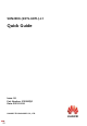
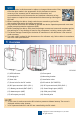
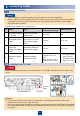
2 2.1 3 Installing the Device Installation Requirements Space Angle Mounting Hole Dimensions 2.2 Installing the Solar Inverter 1. Install the mounting bracket. Avoid drilling holes in the water pipes and cables buried in the wall.
• • • • M6x60 expansion bolts are delivered with the solar inverter. If the length and number of the bolts do not meet installation requirements, prepare M6 stainless steel expansion bolts by yourself. The expansion bolts delivered with the solar inverter are mainly used for solid concrete walls. For other types of walls, prepare bolts by yourself and ensure that the wall meets the load bearing requirements of the solar inverter.
3 Connecting Cables 3.1 Preparing Cables • • Connect cables in accordance with the local installation laws and regulations. Before connecting cables, ensure that the DC switch of the solar inverter and all the switches connected to it are set to OFF. Otherwise, the high voltage produced by the solar inverter may cause electric shocks. Prepare cables based on site requirements.
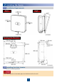
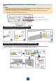
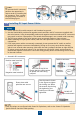
3.3 Installing a WLAN Antenna or Smart Dongle • • If FE communication is used, install a WLAN-FE Smart Dongle (SDongleA-05). You need to purchase the WLAN-FE Smart Dongle by yourself. If 4G communication is used, install a 4G Smart Dongle (SDongleA-03). You need to purchase the 4G Smart Dongle by yourself. Antenna port (ANT) Smart Dongle port (4G/FE) WLAN Antenna (WLAN Communication) Ensure that the WLAN antenna is installed securely.
(Optional) 4G Smart Dongle (4G Communication) • • • • • • • If your Smart Dongle is configured with a SIM card, you do not need to install the SIM card. The configured SIM card can be used only on the Smart Dongle. If your Smart Dongle is not equipped with a SIM card, prepare a standard SIM card (size: 25 mm x 15 mm) with the capacity greater than or equal to 64 KB. Install the SIM card in the arrow direction.
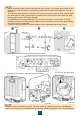
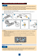
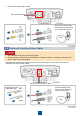
1. Connect the AC output power cable to the AC connector. Three-Core Cable (L, N, and PE) Click The method for connecting a two-core AC output power cable is the same except that the cable is not connected to PE. 2. Connect the AC connector to the AC output port. Check the route of the AC output power cable.
To remove the AC connector, perform the operations in reverse order of installing the AC connector. Then, remove the plug insert, as shown in the following figure. Plug insert 3.5 Installing DC Input Power Cables 1. Ensure that the PV module output is well insulated to ground. 2. Use the Staubli MC4 positive and negative metal terminals and DC connectors supplied with the solar inverter. Using incompatible positive and negative metal terminals and DC connectors may result in serious consequences.
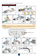
2. Connect DC input power cables. DC input terminals Pull the DC input power cable back to ensure that it is connected securely. Click 3.6 (Optional) Installing Battery Cables • • Use insulated tools when connecting cables. Connect battery cables with correct polarity. If battery cables are reversely connected, the solar inverter may be damaged. Assemble the positive and negative connectors by following the instructions in section 3.5 "Installing DC Input Power Cables.
3.7 (Optional) Installing Signal Cables • • • • When laying out a signal cable, separate it from power cables to avoid strong signal interference. Ensure that the protective layer of the cable is inside the connector, that excess core wires are cut off from the protection layer, that the exposed core wire is totally inserted into the cable hole, and that the cable is connected securely. Block the unused cable hole using a cap and tighten the cable gland.
Crimping Three Signal Cables Connecting Signal Cables Number of Communications Cables Click 4 Verifying the Installation No. Acceptance Criteria 1 The solar inverter is installed correctly and securely. 2 The WLAN antenna is installed correctly and securely. 3 Cables are routed properly as required by the customer. 4 Cable ties are evenly distributed and no burr exists. 5 The PE cable is connected correctly and securely.
5 • • Powering On the System Before turning on the AC switch between the solar inverter and the power grid, check that the AC voltage is within the specified range using a multimeter set to the AC position. If the solar inverter is connected to an LG battery, turn on the DC switch within 1 minute after turning on the AC switch. If you turn on the DC switch after more than 1 minute, the solar inverter will shut down and start again. 1. If a battery is connected, turn on the battery switch. 2.
Type Status (Blinking at long intervals: On for 1s and then Off for 1s; Blinking at short Intervals: On for 0.2s and then Off for 0.2s) Communication LED3 indication Device replacement indication 6 • • • Meaning N/A Blinking green at short intervals Communication is in progress. Blinking green at long intervals A mobile phone is connected to the solar inverter. Off There is no communication. LED1 LED2 LED3 N/A Steady red Steady red Steady red The solar inverter hardware is faulty.
6.2 (Optional) Registering an Installer Account If you already have an installer account, skip this step. Creating the first installer account will generate a domain named after the company. xxx Installer 14 To create multiple installer accounts for a company, log in to the PV Monitor app and tap Add User to create an installer account.
6.3 Creating a PV Plant and a Plant Owner • • In the quick settings, the grid code is set to N/A by default (automatic startup is not supported). Set the grid code based on the area where the PV plant is located. For details, see the FusionSolar App Quick Guide. You can scan the QR code to download the quick guide. 6.
2. Log in to https://intl.fusionsolar.huawei.com to access the WebUI of the FusionSolar Smart PV Management System. On the Home page, click the plant name to go to the plant page. Select layout. Choose Generate layout, and create a physical layout as prompted. You can also manually create a physical location layout. You can also upload the physical layout template photo on the WebUI as follows: Log in to https://intl.fusionsolar.huawei.com to access the WebUI of the PV Monitor Smart PV Management System.
6.5 Setting Battery Parameters If the solar inverter connects to batteries, set battery parameters. 1. Log in to the FusionSolar app and choose My > Device commissioning. The Device commissioning screen (Refer to 7.1 Device Commissioning.) is displayed. 2. Choose Power adjustment > Battery control and set battery parameters, including Charge from grid, Control mode (Fully fed to grid, TOU(Time-of-use), Maximum self-consumption), and so on. 7 FAQ 7.1 Device Commissioning 1. Access Device commissioning.
2. Connect to the solar inverter WLAN and log in as installer to access the device commissioning screen. 7.2 Resetting the Password 1. Ensure that the SUN2000 connects to the AC and DC power supplies at the same time. Indicators and are steady green or blink at long intervals for more than 3 minutes. 2. Perform the following operations within 3 minutes: a. Turn off the AC switch and set the DC switch at the bottom of the SUN2000 to OFF. If the SUN2000 connects to batteries, turn off the battery switch.
9 Customer Service Contact Information Customer Service Contact Region Country Service Support Email Phone eu_inverter_support@huawei.com 0080033888888 France Germany Spain Europe Italy UK Netherlands Other countries For details, see solar.huawei.com. Australia eu_inverter_support@huawei.com 1800046639 Turkey eu_inverter_support@huawei.com N/A 0080021686868 /1800220036 Malaysia apsupport@huawei.
Huawei Technologies Co., Ltd Huawei Industrial Base, Bantian, Longgang Shenzhen 518129, People's Republic of China solar.huawei.