OPERATING AND MAINTENANCE MANUAL FOR COMMERCIAL SOLAR WATER HEATER ELECTRIC HEATER COMPANY BASE MODEL “SLN”
HUBBELL ELECTRIC HEATER COMPANY P.O. BOX 288 STRATFORD, CT 06615 PHONE: (203) 378-2659 FAX: (203) 378-3593 INTERNET: http://www.hubbellheaters.com/ -- IMPORTANT -Always reference the full model number and serial number when calling the factory. WARNING / CAUTION 1. Tank is to be completely filled with water and all air is to be vented before energizing. 2. Due to the rigors of transportation, all connections should be checked for tightness before heater is placed in operation. 3.
TABLE OF CONTENTS SECTION TITLE PAGE # I GENERAL DESCRIPTION AND CONSTRUCTION 5 II INSTALLATION 8 III SCHEDULED MAINTENANCE AND OPERATION 11 IV TROUBLESHOOTING 13 V SERVICING AND REPLACEMENT OF PARTS 15 3
SECTION I - GENERAL DESCRIPTION AND CONSTRUCTION GENERAL DESCRIPTION This book describes a packaged solar water heater that is a stationary, self-contained unit. The complete assembly on a standard unit consists of the storage tank, immersion heating coil, and an ASME rated combination temperature and pressure safety relief valve.
OUTER SHELL AND INSULATION The tank is encapsulated in 2-inch thick polyurethane foam insulation. The insulation is protected by a high impact non-corroding colorized composite protective jacket. THERMISTOR CLIP The water heater is supplied with a thermistor clip located just above the heating coil tank flange for attaching a sensing probe to the water heater tank. Temperature sensors and controls are not included with the water heater.
Temperature High Limit Switch As a safety device, either a surface mounted high temperature cut-off switch with manual reset, factory set at 190° F, or an immersion high temperature cut-off switch with manual reset, factory set at 180° F, may be provided. In the event of an over-temperature condition, the thermostat will disengage the power from the back-up electric heating system. The high limit must be manually reset thereafter to restart the heater.
SECTION II – INSTALLATION WARNING / CAUTION DO NOT TURN ON THE SOLAR WATER SUPPLY to this equipment until heater is completely filled with water and all air has been released. If the heater is NOT filled with water when the power is turned on, damage to the heating coil may result.
PIPING INSTALLATION NOTE: The most effective means for preventing deterioration from accelerated corrosion due to galvanic and stray current is the installation of dielectric fittings/unions. The installation of these fittings is the responsibility of the installing contractor. 1. All integral components have been properly sized to meet design conditions. Piping to the unit should be sized to meet the design conditions, as dictated by good engineering practices. 2.
Outlet to floor drain Install into provided tapping Manual Release Lever Temperature Probe Temperature and Pressure Relief Valve 5. Install a relief valve overflow pipe to a nearby floor drain. CAUTION: No valve of any type should be installed between the relief valve and tank or in the drain line. ELECTRICAL INSTALLATION 1. Connect thermistor to thermistor clip. 2. If supplied with a back-up electric heating element; enter electric junction box with properly sized feeder leads.
SECTION III - SCHEDULED MAINTENANCE AND OPERATION WARNING / CAUTION Before performing any maintenance procedure, make certain solar water and electric supply is OFF and cannot accidentally be turned on. MAINTENANCE AND OPERATION The water heater is automatic in its operation. It will maintain a full tank of water at the temperature setting of the thermostat. The water heater should not be turned on without first making sure that the tank is full of water and that all air has been released.
ANNUAL INSPECTION 1. Flush tank as follows a. b. c. d. Shut off power supply. Close valve on hot water outlet piping. Open valve on drain piping. Cold water inlet line pressure will be strong enough to flush sediment from the bottom of the tank out through the drain. Let water run for 3-4 minutes. e. Close drain valve. f. Open hot water valve. g. Turn power supply ON. 2. Units subject to exterior fouling or scaling should be cleaned periodically.
SECTION IV – TROUBLESHOOTING SOLAR WATER SYSTEM Symptom Gradual loss of heating capacity. Overheating. Immediate loss of heating capacity. Excessive vibration. Water hammer. Probable Cause Tubes are fouled. Corrective Action / Remedy Clean tubes per Section III, annual scheduled maintenance. Excess silt in bottom of tank. Drain and flush tank per Section III , annual scheduled maintenance. Ruptured tube(s) in heating Remove / replace heating coil. coil. Thermostat needs adjusting.
BACK-UP ELECTRCIAL HEATER SYSTEM (if supplied) Symptom No hot water Probable Cause Circuit breaker tripped at source. High limit switch tripped. Loose wires. Heating element inoperable. Low line voltage. Faulty thermostat. Water temperature below settings at all times Faulty thermostat. Heating element not working on all phases Heater improperly sized Relief valve discharges continuously 14 Excessive temperature or pressure in tank Corrective Action / Remedy Reset circuit breaker.
SECTION V - SERVICING & REPLACEMENT OF PARTS WARNING / CAUTION Before servicing or replacing any part make sure to turn the power supply switch to the OFF position. RELIEF VALVE 1. Disconnect power from unit. 2. Shut off incoming cold and solar water supply. 3. Lift test lever on relief valve to relieve pressure in tank. 4. Disconnect overflow piping. 5. Unscrew relief valve, remove assembly and replace with new one. 6. Connect overflow piping. 7. Turn on incoming water supply and check for leaks. 8.
HEATING COIL 1. Disconnect power from unit. 2. Shut off incoming cold and solar water supply. 3. Attach hose to drain connection. 4. Lift manual release lever on relief valve to let air into system or break union on outgoing water line. 5. Drain water from tank. 6. Remove access cover. (See diagram on page 9). 7. Disconnect supply and return lines from heating coil. 8. Remove bolts securing the heating coil to the tank flange. 9. Withdraw heating coil assembly. 10.
HEATING ELEMENT (if supplied) 1. Disconnect power from unit. 2. Shut off incoming water supply. 3. Attach hose to drain connection. 4. Lift manual release lever on relief valve to let air into system or break union on outgoing water line. 5. Drain water from tank. 6. Disconnect the wires from the heating element terminals. Tank Flange Wires 7. Remove the 3/8-16 nuts. 8. Withdraw element assembly and remove gasket. Gasket Element Assembly Nuts 9. Install new gasket and insert new heating element. 10.
L1 L1 L2 L3 L2 1 3 2 1 3 2 4 1 4 2 1 2 1 3 2 Single Element Operation 1 4 2 3 Ø Open Delta Wiring for Simultaneous Operation 18
L1 1 2 L2 L1 3 4 1 1 2 L2 3 4 1 4 4 2 2 1 1 2 2 Interlocked for Non-Simultaneous Operation Non-Interlocked for Simultaneous Operation 19
SURFACE MOUNTED THERMOSTAT (if supplied) 1. Disconnect power from unit. 2. Remove access cover and locate thermostat. 3. Disconnect the two (2) or three (3) 14 gauge wires and jumpers, as required. Control Wires 4. Remove two (2) mounting screws and disconnect from high limit cut-off, if required. Mounting Screws 5. Replace thermostat using the reverse procedure.
IMMERSION THERMOSTAT (if supplied) 1. Disconnect power from unit. 2. Remove access cover and locate thermostat. 3. Remove high limit cover screw and cover. Cover Cover Screw 4. Disconnect the two (2) or three (3) 14 gauge wires, as required. Wires Capillary Tube 5. Remove capillary tube and bulb from thermowell. 6. Remove two (2) mounting screws. Mounting Screws 7. Replace thermostat using reverse procedure. (Note: Be sure to place capillary tube into slot in base prior to installing cover.
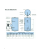
Model SLN – Coil Curves