Hubbell Industrial Controls, Inc. HUBBELL A subsidiary of Hubbell Incorporated 50 Edwards St. Madison, OH 44057 Telephone (440) 428-1161 FAX (440) 428-7635 Instruction Manual Fire Pump Controller Model LX-1500 Limited Service Electric Publication No.
Limited Service Fire Pump Controller Table of Contents I Introduction..................................................................................................................................3 II Specifications and Certifications ................................................................................................3 Specifications ................................................................................................................................3 Certifications ...............
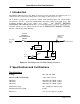
Limited Service Fire Pump Controller I Introduction The Hubbell Limited Service Fire Pump Controller provides automatic and manual control of small electric motor driven fire pumps and booster pumps of 30 horsepower or less. All Controller components are inside the cabinet with indicating lights and switch handles located next to the door. A pressure switch initiates automatic starting of the pump motor. The Controller monitors the power phases and voltage.
Limited Service Fire Pump Controller Undervoltage Trip 15% below set point Time Delays Pick-up, 1.5 s, fixed Drop-out, 1.5 s, fixed Output Relays 10 A, 120 VAC 5 A, 240 VAC Indication green LED, on for A-B-C phase rotation Surge Suppressor 650 V rating Temperature Operating: −4° F to 104° F (−20° C to 40° C) Storage: −4° F to 182° F (−20° C to 85° C) Certifications The Hubbell Limited Service Electric Fire Pump Controller is built to NFPA 20 requirements.
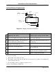
Limited Service Fire Pump Controller Caution: Before drilling and punching holes in the cabinet for wiring connections, cover the components inside the cabinet with a protective covering. Debris may cause shorts or prevent operation of components. 6. Punch holes in the top or the bottom of the cabinet for conduit. 7. Connect the water pressure sensing line to the PS (1/4 NPT internal, 3/4-16 external, brass) fitting on the bottom of the cabinet. For further details, consult the latest edition of NFPA 20.
Limited Service Fire Pump Controller still timing, the CR relay remains energized and the motor continues to run for the duration of the timer setting. Pressing the STOP push button stops the motor even if TR1 is timing. If the Controller does not have a TR1 timing relay, the pump motor runs until the STOP push button is pressed. Manual Local Start - Pressing the START push button energizes relay LRSR. The LRSR contacts close to latch the LRSR relay and energize the M1 contactor coil to start the motor.
Limited Service Fire Pump Controller VI Start Up Procedure Danger: Shocks, burns, or death may result from high voltage. Caution: Only personnel who are familiar with the power distribution system and this manual should be allowed to perform this procedure. 1. Verify that the motor nameplate horsepower and voltage match the Controller nameplate. 2. Verify that the CIRCUIT BREAKER DISCONNECTING MEANS is open. Check with the electrician to see if the Controller is connected directly to the main transformer.
Limited Service Fire Pump Controller 11. Press the STOP push button to stop the motor. 12. Start and stop the motor with the EMERGENCY MANUAL CONTROL handle. Push and rotate the T-handle in a quick motion to lock the contactor in the ON position to start. Rotate the T-handle clockwise and release to stop the motor. Caution: Failure to engage the handle in a fast and continuous motion can result in damage to the contactor and failure to start the motor.
Limited Service Fire Pump Controller VII Maintenance Danger: Do not open the Controller cabinet until ALL power is disconnected. Shocks, burns, or death may result from high voltage. Caution: Only personnel who are familiar with the power distribution system and this manual should be allowed to inspect or perform maintenance on the Controller. Preventive Maintenance A. Protect the equipment against accumulation of dust and metal chips. B.
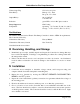
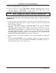
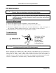
Limited Service Fire Pump Controller Coil and Contact Replacement Coil Retainers Spring Clip Coil Magnet Assembly Figure VI-1 Magnet Assembly and Retainers Coil Replacement* Contact Replacement* 1. Isolate all power sources. Complete steps 1 through 5 in left column. 2. While pressing against the coil, pull up slightly on the coil retainers and swing away from coils. Remove the magnet assembly from the molded cover and movable arm. 3.
Limited Service Fire Pump Controller VIII Limited Service Fire Pump Controller Parts Spares Symbol Description Function Part No. 1 1 CR, LRSR LK, PFR, PRR High Voltage Relay 2-Pole Relay Starting Relay Control Relay 31658141 31658123 2 FU1, FU2 Fuse, 1 A, MDL-1 Control Power 57361726 1 TR1 Timing Relay, octal Min.
Limited Service Fire Pump Controller Spares Symbol Description CB (Note 3) Breaker, 15 A Breaker, 20 A Breaker, 25 A Breaker, 30 A Breaker, 40 A Breaker, 50 A Breaker, 60 A Breaker, 70 A Breaker, 90 A Breaker, 110 A Breaker, 125 A Breaker, 150 A M1 Contactor, 200/208 Contactor, 220/240 Contactor, 440/480 Function Circuit Breaker Discounting Means Main Contactor Contactor Coil, 200/208 Contactor Coil, 220/240 Contactor Coil, 440/480 M1a1, M1b1 Auxiliary Contact, M1 Part No.