
User Manual
ManualsBrandsHubbell ManualsCommercial Dish Washing EquipmentBooster Heater Electric, 24.0 kW with 16-Gallon Storage Capacity, ASME Stamped Stainless Steel Tank with CFC/HCFC Free Closed Cell Foam insulation, Electronic Display Controller with Low Water Cut-Off and Leak Detection, Stainless Steel Exterior, Pressure

18
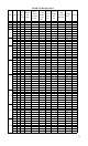
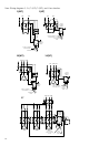
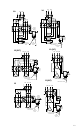
Note: Wiring diagrams 3, 5, 6, 7 (NT), 7 (WT), and 11 are obsolete.
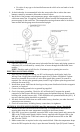
1(WT)
L1
L2
J5
J3
J2
Control, Low Water,
& Hi-Limit Probe
Leak Detection Probe
Control
Module &
Display
1(NT)
L1 L2
J5
J3
J2
Control, Low Water,
& Hi-Limit Probe
Leak Detection
Probe
Control
Module &
Display
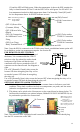
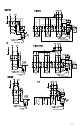
J8
J8
L1 L2 L3
J5
J3
J2
J8
17
Control
Module &
Display
Control, Low
Water, & Hi-Limit
Probe
Leak
Detection
Probe
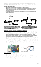
10(WT)
L1 L3L2
J5
J3
J2
Control, Low Water,
& Hi-Limit Probe
Leak Detection
Probe
Control
Module &
Display
10(NT)
L1 L3L2
J5
J3
J2
Control, Low Water,
& Hi-Limit Probe
Leak
Detection
Probe
Control
Module &
Display
J8
J8
J7
J7
J7
J7
J7
J4
J1
XB1
JX5
JX
4
JX
6