
User's Manual


TSS 2. Generation
Tire Safety System TSS 2nd. Generation
Dept. BEE
Dokument Nr.:
Document no.:
Änderungsstand:
Status of
modification:
Index:
Index:
3530.001.002.00.27
00 c
Systembeschreibung TSS
System description TSS
freigegeben am /date of release
17/01/07
Contents:
1
SYSTEM AND FUNCTIONAL DESCRIPTION ................................................................................................. 5
1.1
S
YSTEM DESCRIPTION
.................................................................................................................................................5
2
FUNCTIONAL DESCRIPTION ............................................................................................................................ 6
3
WARNING ALGORITHM..................................................................................................................................... 8
3.1
W
ARNING LIMIT
“M
INIMUM PRESSURE
” ..................................................................................................................... 8
3.2
W
ARNING LIMIT
“N
OMINAL PRESSURE MINUS RELATIVE DEVIATION
” (N
OMINAL PRESSURE
–
X
%) .......................... 8
4
SYSTEM COMPONENTS...................................................................................................................................... 8
4.1
C
ONTROL UNIT
............................................................................................................................................................ 8
4.1.1
Installation area.................................................................................................................................................9
4.1.2
Temperature range............................................................................................................................................. 9
4.1.3
Voltage Range....................................................................................................................................................9
4.1.4
Current consumption ......................................................................................................................................... 9
4.1.5
Occupancy of the CAN control unit:..................................................................................................................9
4.1.6
Occupancy of the K bus control unit: ..............................................................................................................10
4.1.7
CAN bus connection.........................................................................................................................................10
4.1.8
K bus connection..............................................................................................................................................10
4.2
W
HEEL ELECTRONIC
.................................................................................................................................................10
4.2.1
Installation area...............................................................................................................................................11
4.2.2
Versions ...........................................................................................................................................................11
4.2.3
Temperature..................................................................................................................................................... 11
4.2.4
Pressure ...........................................................................................................................................................12
4.2.5
Service Life.......................................................................................................................................................12
4.2.6
Environmental requirements............................................................................................................................12
4.2.7
Mechanical specification .................................................................................................................................13
4.2.8
Measurement specification ..............................................................................................................................13
4.2.9
Specification for HF transmitter ......................................................................................................................13
•
Transmitting power..................................................................................................................................................14
4.2.10
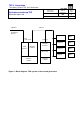
Block diagram wheel electronics .....................................................................................................................14
4.3
D
IGITAL
A
NTENNA
.................................................................................................................................................... 15
4.3.1
Installation Area ..............................................................................................................................................15
4.3.2
General Dimensions and Values......................................................................................................................15
4.3.3
Temperature ranges .........................................................................................................................................15
4.3.4
Voltage supply..................................................................................................................................................15
4.3.5
Current consumption .......................................................................................................................................15
4.3.6
Environmental conditions ................................................................................................................................15
4.3.7
TSS BUS communication with TSS control unit...............................................................................................16
4.3.8
Connection occupancy, sleeve strip ................................................................................................................16
4.3.9
Block diagram..................................................................................................................................................16
4.3.10
Assembly ..........................................................................................................................................................17
4.4
T
RIGGER
T
RANSMITTERS
.......................................................................................................................................... 18
4.4.1
Temperatur / temperature ................................................................................................................................18
4.4.2
Mechanische Anforderungen / mechanical requirements ................................................................................18
4.4.3
Voltage Range..................................................................................................................................................18
4.4.4
CurrentConsumption........................................................................................................................................18