Owner’s Manual for Multi Speed Bicycles This Owner's Manual contains assembly, operation, and maintenance instructions. WARNING: - Check operation of brakes every time before bicycle is ridden. The rider must wear a helmet. Do not ride at night. Check on local bicycle laws before bicycle is ridden. Read the entire Owner's Manual before bicycle is assembled, ridden, or maintenance work is performed.
HBC Limited Warranty Part or model specifications are subject to change without notice. This Limited Warranty is the only warranty for your HBC bicycle. There are no other express warranties. The only uses for this product are described in this manual. Warranty registration is not required. This Limited Warranty extends only to the original consumer and is not transferable to anyone else What does this Limited Warranty cover? This Limited Warranty covers all parts of the bicycle.
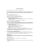
Owner’s Bicycle Identification Record NOTE: This information is only available on the bicycle itself. It is not available from HBC. Each HBC bicycle has a Model / Serial Number stamped into the frame or printed on a label. The Model / Serial Number [1] can be found on the bottom of the crank housing, on the top of the crank housing, or on the rear of the bicycle as shown. Write this number below to keep it for future reference.
The Owner’s Responsibility WARNING: This bicycle is made to be ridden by one rider at a time for general transportation and recreational use. It is not made to withstand the abuse of stunting and jumping. If the bicycle was purchased unassembled, it is the owner’s responsibility to follow all assembly and adjustment instructions exactly as written in this manual and any “Special Instructions” supplied and to make sure all fasteners and components are securely tightened.
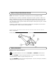
- Purchase, install, and use a headlight and taillight. Headlights are required by all states for nighttime riding and taillights are required in some states. Battery-powered lights or flashing safety lights are also recommended. - Make sure the reflectors of your bicycle are correctly positioned. Do not remove the reflector or replace the reflectors with lighted devices that look similar to reflectors. - Make yourself more visible to motorists.
Introduction This Owner’s Manual is made for several different bicycles. Some of the illustrations may not look exactly like the parts of the bicycle, but the instructions are correct. If the bicycle has any parts that are not described in this manual, look for separate “Special Instructions” that are supplied with the bicycle. Make sure the rear wheel is centered in the bicycle frame. Do not dispose of the carton and packaging until you complete the assembly of the bicycle.
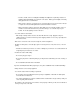
Front Wheel If the bicycle does not have a front fender, go to Step 2. 1. Attach front fender [1] to the fork [2] with screws [9]. 2. Assemble the front wheel to the fork: - If the axle nuts are already attached to the front wheel axle, begin by removing them with an open end wrench or adjustable wrench - Set the wheel into the front fork.
3. Assemble the quick release mechanism to the front wheel: - Remove the adjusting nut [4] and one spring from the quick release mechanism - Put the quick release mechanism through the front wheel hub - Put the spring and adjusting nut back on the quick release mechanism - Do not tighten the adjusting nut at this time. 4. Assemble the front wheel to the fork: NOTE: The words “open” and “close” are on opposite sides of the quick release lever.
WARNING: Failure to obey these steps can allow the front wheel to loosen while riding. This can cause injury to the rider or to others. CAUTION: Operate the quick release lever by hand only. Do not use a hammer or any other tool to tighten the quick release lever. 5. Adjust and tighten the quick release mechanism: WARNING: Do not tighten the quick release mechanism by turning the lever in a circular motion. This causes the clamping force to be too light.
Operation To remove the wheel: - Move the quick release lever to the “open” position. - It is not necessary to turn the adjusting nut to remove the wheel. Before riding the bicycle: - Especially after parking in a public place, always check that the quick release mechanism is properly installed and tightened. - If you are not certain that the quick release mechanism is correctly installed and tightened, do Steps 4 and 5 of these instructions.
Front Reflector Bracket and Clear Reflector Assembly This section covers the assembly of the front reflector to the front reflector bracket. Determine which style you have before beginning assembly. Snap In Style Screw In Style Reflector Assembly 1. Assemble the clear reflector to the front reflector bracket: WARNING: Install the clear reflector exactly as shown or it will not operate correctly.
Front Reflector Bracket Installation This section covers several different placements of the front reflector bracket. Make sure the front reflector is vertical (perpendicular to the ground). The front reflector bracket will mount on the fork or handlebar. Some models may already have the brackets and reflectors installed. If the reflector is not installed, refer to the “Front Reflector Bracket and Clear Reflector Assembly” section.
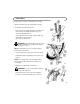
Bottom of Fork 1. Attach the hardware to the fork: - Remove and discard plastic cap [5] on fork [6] - Tighten bearing cone [2] by hand to make sure the bearings are tight - Install sheath stop [3] and locknut [4]. You may not have a sheath stop. If you do not, install a keyed washer and locknut. NOTE: The sheath stop barrel [11] is on the cable wire of the front cantilever brake. Install it during the assembly of the brake. - Tighten locknut. 2.
Rear Reflector Bracket and Red Reflector Assembly This section covers the assembly of the rear reflector to the rear reflector bracket. Determine which style you have before beginning assembly. Snap In Style Screw In Style Reflector Assembly 1. Assemble the red reflector to the rear reflector bracket: WARNING: Install the red reflector exactly as shown or it will not operate correctly.
Rear Reflector Bracket Installation This section covers several different placements of the rear reflector bracket. Make sure the rear reflector is vertical (perpendicular to the ground). The rear reflector bracket will mount on the seat post, post clamp, or rear brace. Some models may already have the brackets and reflectors installed. If the reflector is not installed, refer to the “Rear Reflector Bracket and Red Reflector Assembly” section.
Rear Brace 1. Install bracket on rear brace: - Put bracket on brace so the bracket points up - Install bolt and nut (also washer, if provided) - Tighten securely. Operation and Maintenance WARNING: For your own safety, do not ride the bicycle if the reflectors are incorrectly installed, damaged, or missing. Make sure the front and rear reflectors are vertical. Do not allow the visibility of the reflectors to be blocked by clothing or other articles. Dirty reflectors do not work well.
Style 2 - Push pin - Put fastener [6] over a spoke [7] and into each reflector - Push pin straight into reflector until a "snap" sound is heard. Style 3 - One-quarter turn - Put fastener [6] over a spoke [7] and into each reflector - Turn fastener clockwise one-quarter of a turn. Operation and Maintenance WARNING: For your own safety, do not ride the bicycle if the reflectors are incorrectly installed, damaged, or missing. Make sure the front and rear reflectors are vertical.
Handlebar and Stem The bicycle may have different styles of handlebar stems. One style mounts inside the fork while the other mounts around the outside of the fork. Follow the instructions for the style that you have. Assembly Inside mount 1.
3. Determine the type of parts to be assembled to the handlebar: Following are the various combination of parts that you may have to assemble. Determine which parts are most like what you have and assemble as shown. You may not have some of the parts but assemble the parts you have in the order as shown. You may have to move the handlebar to each side to install some parts.
WARNING: If the handlebar clamp in not tight enough, the handlebar can slip in the stem. This can cause damage to the handlebar or stem, and can cause loss of control. - Tighten the bolt(s) of the handlebar clamp - If the handlebar clamp has more than one bolt, tighten the bolts equally. 5.
- Tighten the clamp screw of each brake lever - Move each bar end around the handlebar to a position that is comfortable to the rider - Tighten the clamp bolt of bar end securely. 8.
Seat Assembly CAUTION: If you accidently drop the seat post into the seat tube, you may not be able to remove it. 1. Install post clamp on seat tube: - Put the clamp on the seat tube. Push the clamp [1] down so you can see 1/16 inch [2] of the seat tube [3] above the clamp. NOTE: Some post clamps are welded in position and can not be moved. - If the post clamp has a raised edge, make sure the raised edge is against the top of the seat tube. 2.
3. Point the seat forward and put the seat post or seat pillar into the seat tube. - Make sure you can not see the “MIN-IN” minimum insertion mark [13] of the seat post above the seat tube - Install a bolt, washer (if supplied), and nut or a quick release lever - Put the seat at a comfortable height for the rider WARNING: The red reflector must be vertical, point straight toward the rear of the bicycle, and have three inches of clearance between the top oft the seat and the top of the red reflector.
4. Test the tightness of each the clamp and the post clamp: WARNING: Every time you loosen the quick release mechanism, make sure the red reflector is correctly positioned if the reflector is mounted on the seat post or seat pillar.
Pedals CAUTION: There is a right pedal marked “R” and a left pedal marked “L”. The pedal marked “R” has right-hand threads. Tighten it in a clockwise direction. The pedal marked “L” has left-hand threads. Tighten it in a counterclockwise direction. 1. Turn the right pedal marked “R” [1] into the right side of the crank and the left pedal marked “L” [2] into the left side of the crank. 2.
Brake Systems Adjustments WARNING: You must adjust the front and rear brakes as written before you ride the bicycle. 1. Put the brake shoes in the correct position: - Loosen the nut [7] of each brake shoe - Adjust each brake shoe so it is flat against the rim and aligned with the curve of the rim - Make sure each brake shoe does not rub the tire - If the surface of the brake shoe has arrows, make sure the arrows point toward the rear of the bicycle - Hold each brake shoe in position and tighten the nut.
The following sections describe final brake system adjustments required before riding. Determine which style you have and follow the instructions. Sidepull Brake Cantilever Brake 1. Check tightness of caliper brake mounting nut or cantilever mounting bolt: - Make sure each caliper brake mounting nut or cantilever mounting bolt is tightened securely. 2.
- Pull or loosen the cable wire slightly - Tighten the cable clamp WARNING: Do not overtighten the cable clamp. Overtightening the cable clamp may cut the cable and cause injury to the rider or to others. - Do Step 3 until the brake shoes are the correct distance from the rim - Turn the locknut(s) against the brake lever and the caliper brake. WARNING: Do not move the brake shoes away from a wheel rim that is not true (straight). This can cause the caliper brake to be less effective and unsafe.
7. Test the travel of each brake lever: - Squeeze each brake lever with strong pressure - If the brake lever touches the grip, do Steps 1 through 7 again. WARNING: After you do Steps 1 through 7 again, if either brake lever touches the grip or does not work well, have a bicycle service shop repair or adjust the caliper or cantilever brakes. Reducing Caliper Brake Noise (Caliper Brake Only) It is common for caliper brakes to make noise or “squeak” when in use.
Operation Operate the brakes as follows: - Squeeze the brake lever on the handlebar - The brake lever pulls on a cable that is attached to the brake - The brake squeezes the rim between two brake shoes. Operate the brakes by slowly and continuously squeezing both brake levers until you feel the braking action. Make a habit of always using both brakes to stop the bicycle. You will stop in the shortest distance by using both brakes.
Accessories Water Bottles Determine which water bottle looks most like the one you have and follow the instructions. WARNING: Do not use a water bottle while riding. Always stop the bicycle before you use the water bottle. NOTE: Thoroughly wash any water bottle before you use it.
Handlebar Bag Attach the bag to the handlebar: - Put bag against the front of the handlebar - Wrap fasteners around the handlebar and push together - Make sure the bag does not cover any reflectors - If the bag covers any reflectors, turn the bag toward the rider - Wrap fasteners around the handlebar and push together.
Kickstand If your model does not already have the kickstand attached, determine which kickstand looks most like the one you have and follow the instructions. CAUTION: Do not sit on the bicycle with the kickstand down. Damage to the kickstand and frame can occur.
Shift System Operation There are two shift levers on the bicycle. The right-hand shift lever operates the rear derailleur and the left-hand shift lever operates the front derailleur.
- They allow you to pedal easier and at a faster rhythm, but with less distance traveled per pedal revolution - For the best performance in this case, do not use the smallest rear sprocket [3] - When riding downhill or with the wind, you may wish to keep the chain on the largest front sprocket [4] and shift the chain on the rear sprocket cluster - These are the higher gear combinations - They allow you to pedal harder and at a slower rhythm, but with more distance traveled per pedal revolution - For the bes
- Turn the “low” adjusting screw so the left inside edge of the chain cage [17] and the chain [18] just do not touch - Remove the slack from the cable wire and tighten the nut of the cable clamp. 2. Put the “high” adjusting screw in the correct position as follows: - Shift the chain onto the largest front sprocket and the smallest rear sprocket - Turn the “high” adjusting screw so the right inside edge of the chain cage and the chain just do not touch.
- Loosen nut of the cable clamp [12] - Turn the “high” adjusting screw so the jockey roller [7] is in line with the outside edge of the smallest rear sprocket [8] - Remove the slack from the cable wire and tighten the nut of the cable clamp. 2.
Repair and Service WARNING: - Inspect the bicycle frequently. Failure to inspect the bicycle and to make repairs or adjustments, as necessary, can result in injury to the rider or to others. Make sure all parts are correctly assembled and adjusted as written in this manual and any “Special Instructions”. - Immediately replace any damaged, missing, or badly worn parts. - Make sure all fasteners are correctly tightened as written in this manual and any “Special Instructions”.
Three-Piece Cranks (on some models) Maintenance Both three-piece crank arms [1] were tightened to the spindle [2] at the factory. After riding the bicycle the first few times, make sure the crank arms have not loosened. If either crank arm has loosened during this “break-in” period, have it tightened by a bicycle service shop, because special tools are necessary. Frequently check the tightness of the crank arms. If loose, have them tightened by a bicycle service shop.
Lubrication Maintenance WARNING: Do not over lubricate. If oil gets on the wheel rims or the brake shoes, it will reduce brake performance and a longer distance to stop the bicycle will be necessary. Injury to the rider or to others can occur. The chain can throw excess oil onto the wheel rim. Wipe excess oil off the chain. Keep all oil off the surfaces of the pedals where your feet rest. Using soap and hot water, wash all oil off the wheel rims, the brake shoes, the pedals, and the tires.
Inspection of the Bearings Maintenance Frequently check the bearings of the bicycle. Have a bicycle service shop lubricate the bearings once a year or any time they do not pass the following tests: Head Tube Bearings The fork should turn freely and smoothly at all times. With the front wheel off the ground, you should not be able to move the fork up, down, or side-to-side in the head tube.
Replacement Part Order List To order warranty replacement parts, call us at (E.S.T.) 1-800-872-2453. To order the correct part, refer to the model number stamped on the inside cover of this manual and substitute it for the “xxxxx” below in our Part Number system. For example, if your model number from the inside front cover is #28206 and you need a new seat, order Part Number 28206-SD. Note-Your model may not look exactly like the representative picture shown.
2
We recommend the following internet sites for helpful information on bicycle assembly, repair and adjustment: www.bicyclerepairshop.com/ members.aol.