Portable System Owners Manual Customer Service Center • N53 W24700 South Corporate Circle • Sussex, WI 53089 • U.S.A. WARNING! REQUIRED TOOLS AND MATERIALS: • Two People • Wood Board (Scrap) • Tape Measure • Step Ladder 8 ft. (2.4 m) • Tape • Garden Hose or Sand 360 lb. (163 kg) • Hammer • Wrenches: (Two) 1/2”, (One) 9/16” or Two Small Adjustable Wrenches (9/16” Deep Socket w/Extension Recommended) • Support Table READ AND UNDERSTAND OPERATOR'S MANUAL BEFORE USING THIS UNIT.
WARNING FAILURE TO FOLLOW THESE WARNINGS MAY RESULT IN SERIOUS INJURY AND/OR PROPERTY DAMAGE. Owner must ensure that all players know and follow these rules for safe operation of the system. • DO NOT HANG on the rim or any part of the system including backboard, support braces or net. • During play, especially when performing dunk type activities, keep player's face away from the backboard, rim and net. Serious injury could occur if teeth/face come in contact with backboard, rim or net.
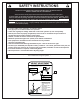
SAFETY INSTRUCTIONS FAILURE TO FOLLOW THESE SAFETY INSTRUCTIONS MAY RESULT IN SERIOUS INJURY OR PROPERTY DAMAGE AND WILL VOID WARRANTY. Owner must ensure that all players know and follow these rules for safe operation of the system. To ensure safety, do not attempt to assemble this system without following the instructions carefully. Check entire box and inside all packing material for parts and/or additional instruction material.
NOTICE TO ASSEMBLERS ALL Huffy Sports Basketball Systems, including those used for DISPLAYS, MUST be assembled and ballasted with sand or water according to instructions. Failure to follow instructions could result in SERIOUS INJURY. It is NOT acceptable to devise a makeshift weight system. IMPORTANT! Remove all contents from boxes. Be sure to check inside pole sections; hardware and additional parts are packed inside.
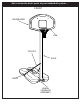
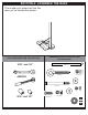
Get to know the basic parts of your basketball system.....
Item Qty. Part No.
HARDWARE IDENTIFIER (BOLTS & RODS) Item #23 (2) Item #8 (1) Item #11 (1) Item #22 (4) Item #7 (1) Item #16 (2) HARDWARE IDENTIFIER (NUTS & WASHERS) Item #10 (1) Item #12 (6) Item #21 (4) Item #17 (6) Item #14 (1) HARDWARE IDENTIFIER (PLASTIC SPACERS & CLIPS) Item #19 (12) Item #28 (2) 7 10/03 P/N 214994C
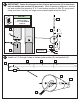
SECTION A: ASSEMBLE THE BASE This is what your system will look like when you’ve finished this section: HARDWARE USED IN THIS SECTION (not actual size) TOOLS REQUIRED FOR THIS SECTION 9/16” and 1/2” Item #7 (1) Item #8 (1) Item #10 (1) AND/OR Item #12 (6) Item #11 (1) Item #14 (1) 9/16” and 1/2” Item #16 (2) Item #17 (6) Item #21 (4) Item #28 (2) P/N 214994C 10/03 8
2. Correctly identify each pole 1. Remove contents from tank section and mark indicated distance from ends with tape (not supplied) as shown. 1 4 TOP TAPE (Not Supplied) MIDDLE 5” (13 cm) 5 6 BOTTOM 5” (13 cm) 3. IMPORTANT! Center the alignment slot of middle pole section (5) in the lower hole of top pole section (4) as shown. While maintaining alignment, bounce middle section of pole (5) into top section of pole (4) using wood scrap as shown until they no longer move toward taped reference mark.
4. IMPORTANT! Center the alignment slot of lower pole section (6) in the lower hole of middle pole section (4) as shown. While maintaining alignment, bounce top and middle pole assembly (4 & 5) onto bottom section of pole (6) using wood scrap as shown until they no longer move toward taped reference mark. NOTE: 4 POLE SECTIONS SHOULD HAVE A 3-1/2" (9 CM) MINIMUM OVERLAP. 5 5 6 6 WOOD SCRAP 5. Install rod (7) through holes in bottom pole section (6) and eyebolt (8).
6. Install wheel axle (2) through wheel carriage (9). Install wheels (3) onto wheel axle (2) with spacers (28) as shown. Insert pole assembly into tank assembly as shown. Secure bottom pole (6) to tank and wheel bracket as shown. A deep socket is recommended. IMPORTANT!: DO NOT OVER TIGHTEN 28 9 3 6 28 3 2 7 IMPORTANT!: WARNING! 8 TWO PEOPLE REQUIRED FOR THIS PROCEDURE. FAILURE TO FOLLOW THIS WARNING COULD RESULT IN SERIOUS INJURY AND/OR PROPERTY DAMAGE.
8. Secure non-secured ends of tank struts (13) to tank as shown. Repeat for opposite side.
SECTION B: ASSEMBLE THE BOARD AND RIM This is what your system will look like when you’ve finished this section: HARDWARE USED IN THIS SECTION (not actual size) TOOLS REQUIRED FOR THIS SECTION 1/2” Item #17 (6) AND/OR Item #19 (12) Item #22 (4) Item #21 (4) Item #23 (2) 1/2” 13 10/03 P/N 214994C
1. Mount brackets (20) and rim (18) to backboard and finger tighten as shown. NOTE: Final adjustments will be made in Step 3 of this section IMPORTANT! For spring loaded rim assembly, refer to instructions included with rim hardware. 22 22 21 18 17 20 IMPORTANT!: 17 P/N 214994C 10/03 Refer to instructions included with rim hardware for backboard and rim assembly.
2. Support pole and tank assembly over support table. Carefully slide backboard components onto pole. WARNING! TWO PEOPLE REQUIRED FOR THIS PROCEDURE. FAILURE TO FOLLOW THIS WARNING COULD RESULT IN SERIOUS INJURY AND/OR PROPERTY DAMAGE. WARNING! DO NOT LEAVE ASSEMBLY UNATTENDED WHEN EMPTY; IT MAY TIP OVER. SAWHORSE OR SUPPORT TABLE 3. While still in the horizontal position, carefully slide backboard components onto pole.
4. Install clips. WARNING! CLIP “ARM” USE OF THIS PRODUCT WITHOUT PROPER INSTALLATION OF SMART CLIPS®, OR WHEN ALL SMART CLIPS® ARE NOT PRESENT COULD RESULT IN BODILY HARM. BE SURE TO FOLLOW DIRECTIONS CAREFULLY. CLIP “BODY” 18 Insert one “arm” of clip into ram as shown. Twist “body” of clip slightly so that second “arm” slides over the top of the first “arm” as shown. Push in direction indicated by arrows. 19 A Push second “arm” back and into ram as shown.
NET INSTALLATION 9. 18 SIDE VIEW 19 NETCLIP 25 NET Insert net into bottom of clip as shown. SIDE VIEW Twist net until it snaps into position. Net must be centered through clip.
SECTION C: APPLY HEIGHT AND MOVING LABEL & SECURING SYSTEM 1. Carefully upright assembly. Apply moving system label (15) to front of pole as shown. Regulation rim height is 10 feet (3.05 m). WARNING! TWO PEOPLE REQUIRED FOR THIS PROCEDURE. FAILURE TO FOLLOW THIS WARNING COULD RESULT IN SERIOUS INJURY AND/OR PROPERTY DAMAGE. 15 10 feet (3.05 m) WARNING! DO NOT LEAVE ASSEMBLY UNATTENDED WHEN EMPTY; IT MAY TIP OVER. 2. Place assembled unit to desired location.
10/03 P/N 214994C Customer Service Center • N53 W24700 South Corporate Circle • Sussex, WI 53089 • U.S.A. Deux personnes Mètre Planche (rebut) Clés: (2) 7/16”, 1/2”, 9/16”, 3/4” ou petite ou grande clé réglabe Lunettes de sécurité Chevalet de scieur ou table de soutien Echelle de 2,4 m (8 pieds) Tuyau d’arrosage ou sable (102 kg) (225 lb.) Marteau Ruban adhésif Tournevis cruciforme Ciseaux POUR REGLER LE PANNEAU : 1. Réglez le panneau de basket-ball à la hauteur la plus basse. 2.
FRENCH INSTRUCTIONS IMPORTANT ! NOTEZ À LA PAGE 1 DE CE MANUEL LE NUMÉRO DE MODÈLE MENTIONNÉ SUR LE CARTON. 12. REMARQUE : Il est recommandé de s'y prendre à deux pour cette procédure. Redressez l'ensemble avec précaution. Collez l'étiquette de déplacement du système (15) sur l'avant du poteau, comme illustré. La hauteur réglementaire du cerceau est de 3,05 m (10 pieds). 1. Retirez le contenu du réservoir (1). 2.
10/03 P/N 214994C Una Compañía Huffy Customer Service Center • N53 W24700 South Corporate Circle • Sussex, WI 53089 • U.S.A. TUFF STUFF® y las marcas comerciales asociadas son propiedad de Mattel, Inc. y se usan con su permiso. Mattel, Inc. y todas sus compañías afiliadas o subsidiarias de ninguna forma patrocinan, aprueban ni autorizan los productos Huffy.
SPANISH INSTRUCTIONS ¡IMPORTANTE! ANOTE EN LA PÁGINA 1 DE ESTE MANUAL DEL PROPIETARIO EL NÚMERO DE MODELO QUE APARECE EN LA CAJA. 1. Saque el contenido del tanque (1). 2. Identifique correctamente cada sección del poste y marque con cinta la distancia indicada desde los extremos, como se muestra. 3. ¡IMPORTANTE! Centre la ranura de alineación de la sección media del poste (5) en el orificio inferior de la sección superior del poste (4), como se muestra.
10/03 P/N 214994C A Huffy Company Customer Service Center • N53 W24700 South Corporate Circle • Sussex, WI 53089 • U.S.A. Zwei Personen Holzbrett (Ausschuß) Bandmaß Treppenleiter, 8 Fuß (2,4 m) Klebeband Gartenschlauch oder Sand (163 kg) (360 US-Pfd.) Hammer Schraubenschlüssel: (Zwei) 1/2 Zoll, (Ein), 9/16 oder verstellbare große und kleine Schraubenschlüssel (9/16-ZollEinsatz mit Verlängerung empfohlen) Sägebock oder Auflagetisch Schutzbrille TRANSPORT DES SYSTEMS 1.
GERMAN INSTRUCTIONS WICHTIG! NOTIEREN SIE SICH DIE MODELLNUMMER AUS DEM KÄSTCHEN AUF SEITE 1 DIESES BENUTZERHANDBUCHS 1. Den Tank (1) leeren. 2. Jedes Stangenteil richtig identifizieren und den angegebenen Abstand von beiden Enden wie gezeigt mit Klebeband markieren. 3. WICHTIG! Den zur leichteren Ausrichtung vorgesehenen Schlitz am mittleren Stangenteil (5) wie gezeigt in einem tieferen Loch des oberen Stangenteils (4) zentrieren.