H-MTB EN 030117 m0012 © Copyright Huffy Corporation 2017 EN Owner’s Manual for Mountain Bikes This manual contains important safety, assembly, operation and maintenance information. Please read and fully understand this manual before operation. Save this manual for future reference.
Owner’s Manual Index Your Bike • Owner’s Bicycle Identification Record.............................................................................3 • Fitting the Rider to the Bicycle...........................................................................................3 • Warning and Safety Information.......................................................................................4 • The Owner’s Responsibility - Rules of the Road.........................................................
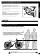
Owner’s Bicycle Identification Record NOTE: This information is only available on the bicycle itself. It is not available from Huffy. Your Bike Each Huffy bicycle has a Recovery Code stamped into the frame. The Recovery Code can be found on the bottom of the crank housing as shown. Write this number below to keep it for future reference. If the bicycle is stolen, give this number and a description of the bicycle to the police. This will help them find the bicycle.
Warning and Safety Information Warning and Safety Meanings of Warnings: This symbol is important. See the word “CAUTION” or “WARNING” which follows it. The word “CAUTION” is before mechanical instructions. If you do not obey these instructions, mechanical damage or failure of a part of the bicycle can occur. The word “WARNING” is before personal safety instructions. If you do not obey these instructions, injury to the rider or to others can occur. • CHOKING HAZARD. Small parts.
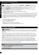
WARNING: Failure of the rider to obey the following “Rules of the Road” can result in injury to the rider or to others. • Obey all traffic regulations, signs, and signals. • Always wear a bicycle helmet that meets safety standards, as well as local safety standards. • Ride on the correct side of the road, in a single file, and in a straight line. • If possible, avoid riding at night, dusk, dawn and any other time of poor visibility.
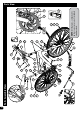
12 11 18 16 17 9 10 15 39 31 Parts Assembly View 29 23 8 35 24 22 30 27 13 14 26 19 36 20 21 1 2 15 34 6 7 5 28 4 25 33 32 40 41 38 NOTE: All features, components and accessories are not included on all models.
Grips (x2) Crank & Spindle Set Crank Bearings 19 20 21 Derailleur Guard 12 Rear Wheel Assembly Guard Screws (x2) 11 18 Rear Reflector 10 Tube (x2) Seat Post 9 17 Seat 8 Tire (x2) Front Reflector 7 16 Axle Nut (x4) Pedal (Left & Right Set) Wheel Retainer (x2) 5 6 15 Fork 4 Frame Front Wheel Assembly 3 Quick Release Lever & Nut Handlebar 2 14 Handlebar Stem 1 13 Description No.
Assembly Introduction to Assembly This Owner’s Manual is made for several different bicycles: • Some illustrations may vary slightly from the actual product. • Follow instructions completely. • If the bicycle has any parts that are not described in this manual, look for separate “Special Instructions” that are supplied with the bicycle. • Models may have different accessory items such as bags, baskets, reflectors, cup holders, racks, etc.
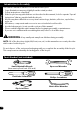
Accessories (various models) BAG OR BASKET INSTALLATION: A B Assembly or Basket to Handlebar using • Attach Bag the two Straps. • Tighten Straps so Bag/Basket does not move. NOTE: Do not over tighten. The Straps may break. B A HANDLEBAR BELL INSTALLATION: 1. Remove screws from Bell. 2. Position Bell on handlebar within easy reach, with hands on the handlebar grips. 3. Install screws and tighten. NOTE: Bell may attach with 1 or 2 screws. WATER BOTTLE AND CAGE: 1. 2. 3.
Assembly Handlebar and Stem Installation WARNINGS: • To prevent steering system damage and possible loss of control, the “MIN-IN” (minimum insertion) mark on the stem must be below the top of the Fork Locknut . • The Front Brake (if equipped) must be positioned in FRONT of the Fork. Ensure the Fork is pointing FORWARD before proceeding. • Do not over tighten the stem bolt. Over tightening the stem bolt can damage the steering system and cause loss of control.
Handlebar and Stem Installation - Threadless Stem: I B G F A B A E B C D NOTE: Ensure there is BETWEEN 1mm and 6mm gap between Fork Tube and . top of Stem 5. Assembly CAUTION: • Threadless Stem should be installed with bike sitting on the ground and both wheels installed. • Make sure Fork is fully inserted from the bottom and Front Brake is pointing FORWARDS. • Disc Brake models: Disc Brake will generally be on the LEFT side of the Fork. STEP 1: as needed for 1. Add Spacers proper Gap . 2.
Handlebar Installation - various Stem Clamps ONE BOLT STEM: Assembly 1. 2. B If necessary, loosen the Handlebar Clamp Bolt(s) and rotate Handlebar into a comfortable riding position. Tighten Handlebar Clamp Bolts(s) securely. A A B A See Torque Table for recommended torque. TWO BOLT STEM: 1. 2. If necessary, loosen the Handlebar Clamp Bolt(s) and rotate Handlebar into a comfortable riding position. Tighten Handlebar Clamp Bolts(s) securely. A B A B A See Torque Table for recommended torque.
Installing the Front Wheel B A B C Install the Front Wheel: 3. Set the Front Wheel into the front fork with Brakes pointing forward. 4. Install wheel retainers making sure the tabs are in the Fork Retainer Holes . 5. Attach the front wheel with the Axle Nuts . - See Torque Table for recommended torque. C A A Assembly Loosen the Front Brakes: 1. Squeeze the two Brake arms together . 2. Lift out the Brake Cable Guide from the Guide Bracket .
Assembly Quick Release Axle Guide (various models) WARNING: Check QR axle and secure before every ride. If you hear any unusual noise from the wheels when riding - check the QR axle system. Do not ride with improperly adjusted or worn QR axle, this can result in serious injury. If you have any problems with the QR axle system, contact the bicycle manufacturer or a local bicycle shop. • This product is not intended for use in stunt riding, ramp jumping, acrobatics, or similar activities.
STEP 3: A • Ensure QR Lever is tight and fully closed. • Ensure wheel is centered in fork and held securely. Wheel shown with QR Lever Closed position. CLOSED OPEN A A in Assembly Quick Release Axle Guide - continued A Closed Open B B WARNING: • Ensure the Quick-Release (QR) is properly tightened before each ride (refer to QR use instructions in this manual). • Ensure QR Lever does not come in contact with Disc Brake or Spokes before each ride. • DO NOT RIDE WITH THE QR IN THE OPEN POSITION.
Testing Stem and Handlebar Tightness Assembly TO TEST THE TIGHTNESS OF THE STEM: • Straddle the front wheel between your legs. • Try to turn the front wheel by turning the handlebar. • If the handlebar and stem turn without turning the front wheel, realign the stem with the wheel and tighten the stem bolt(s) tighter than before (about 1/2 revolution only at a time). • Do this test again, until the handlebar and stem do not turn without turning the front wheel.
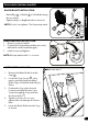
Seat Installation WARNING: To prevent the Seat coming loose and possible loss of control, the “MIN-IN” (minimum insertion) mark on the Seat Post must be below the top of the Seat Tube . A C SEAT AND SEAT POST SETUP: 1. If needed, loosen Nuts on Seat Clamp and rotate Seat into riding position. 2. Ensure the Seat Post is fully through the TOP Seat Clamp . 3. Tighten the Seat Clamp so the Seat does not move on the seat post. 4. If the Seat Clamp has a Nut on each side, tighten both nuts equally. 5.
Seat Installation - continued G Assembly 6. Post Clamp . The tightening torque of the Quick Release Lever should be tight enough so that the seat does not move during normal operation. Seat Bolt Mount (various models) I Some models have a Bolt , Washer and Nut instead of a Quick Release Lever. • If needed, loosen the nut enough to insert the Seat Post . • Point the seat forward and insert Seat Post to the Minimum Insertion marks . • Tighten Nut securely so it supports the rider without moving.
CAUTION: There is a RIGHT pedal marked R and a LEFT pedal marked L. L NOTE: A Pedal Wrench is preferred for attaching Pedals. A thin open-end wrench can also be used. Assembly Pedal Installation • The pedal marked R has right-hand threads. Tighten it in a clockwise direction. • The pedal marked L has left-hand threads. Tighten it in a counterclockwise direction (anti-clockwise).
Reflector Installation (as equipped) Reflector Installation: 1. Position FRONT Reflector so it points straight forward. 2. Tighten Clamp Screw. 3. Position Seat Post Reflector (if equipped) so it points straight backwards. 4. Tighten Clamp Screw. B Assembly A A B NOTE: Do not over-tighten. This will damage the Clamp. Dual Rear Reflectors (various models): A The Rear Reflectors may be pre-installed on the bike chain stays. Make sure they are secure, not bent and are pointing straight backwards.
Linear Pull Brake System Adjustment - Before Starting • Inflate Tires to recommended pressure on Tire side wall. • Make sure Tire is centered in Fork. • If Needed, Re-attach Front Brake Cable: • Squeeze the two Brake arms together . • Insert the Brake Cable Guide into the cutout in the Guide Bracket . • Make sure the Brake Cable Guide is seated securely in the Guide Bracket cutout. A B Brake System IF EQUIPPED: The Following Sections Describe Final Brake System Adjustments Required Before Riding.
Linear Pull Brake System - Adjustment continued Brake System NOTE: The front and rear break adjustments are the same. WARNING: You must adjust the fig B front and rear brakes before you ride the bicycle. Step 1: Put the brake shoes rect position (fig B): 1. 2. 3. 4. 5. C B B in the cor- A Loosen the Screw of each Brake Shoe . Adjust each Brake Shoe so it is flat against the rim and aligned with the curve of the rim. Make sure each Brake Shoe does not rub the tire.
Linear Pull Brake System Adjustment - continued 1. 2. 3. 4. 5. A E Brake System PUT THE BRAKE SHOES THE CORRECT DISTANCE FROM THE RIM: G If desired, adjust Brake Levers to a comfortable distance from the grip using the Adjustment Screw . Turning the screw IN brings it closer to the grip. Make sure brake line Sheaths , are seated correctly. Position each Brake Shoe 1/16 inch away from the rim: Turn the caliper brake adjusting Screws in or out to make the adjustment.
Linear Pull Brake System - continued Brake System Test the tightness of the cable clamp (fig C): 1. 2. 3. G 1. 2. with strong pressure Squeeze each Brake Lever If the brake lever touches the grip, adjust the brakes again. Squeeze each Brake Levers with firm pressure. Make sure the cable does not move in the Cable Clamp . If the cable moves in the cable clamp, adjust the brakes again but tighten the cable clamp tighter than before. 4.
Disc Brake System Adjustment: (various models) fig A F G C E Brake System NOTE: See Torque Table for recommended torques. B A D BRAKE ADJUSTMENT (see fig-A): . 1. Loosen the Cable Clamp Bolt 2. Push the Brake Arm toward the Adjusting Barrel (this applies the brake). 3. While holding the Brake Arm, pull the slack out of the Cable End (through the Cable Clamp) and tighten the Cable Clamp Bolt . A B C D A WARNING: Do not over tighten the Cable Clamp.
Disc Brake System - continued Brake System C Adjusting Barrel on the Caliper. Turn the Adjusting Barrel OUT to tighten the brakes or IN to loosen the brakes. NOTE: Make sure the Adjusting Barrel threads are fully engaged. Check adjustment again. 8. If you cannot reduce the gap by turning the Adjusting Barrel, the brake pads might be worn out and need to be replaced. PAD REPLACEMENT: 1. Remove the Caliper Mounting Bolts . 2. Remove the Caliper assembly . 3. Remove the Brake Pads from the Caliper. 4.
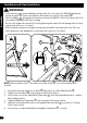
PARTS OF THE SHIFT SYSTEM: • Left-hand Shifter operates the Front Derailleur • Right-hand Shift Lever operates the Rear Derailleur • Front Sprocket Set • Rear Sprocket Set A A B C C D E F B Shift System Shift System E F D WARNING: • Never shift a derailleur onto the largest or the smallest sprocket if the derailleur is not shifting smoothly. The derailleur may be out of adjustment and the chain could jam, causing loss of control and injury.
Shift System Shift System - continued CAUTION: Do not force the shift levers. Shift only when pedaling forward and without strong force. Do not backpedal. Backpedaling can cause the chain to come off the sprockets. Backpedaling and shifting while not pedaling can damage the sprockets and stretch the cable wire. There is no “correct gear” in which to ride the bicycle. The “correct gear” is the one that is comfortable to you. To select a gear or sprocket combination while riding: 1.
Shift System - continued E Shift System THESE ARE THE HIGHER GEAR COMBINATIONS: D fig 03 • They allow you to pedal harder and at a slower rhythm, but with more distance traveled per pedal revolution. • For the best performance in this case, do not use the largest rear sprocket . E THESE ARE THE MIDDLE RANGE GEAR COMBINATIONS: F fig 04 • These overlap some of the higher and some of the lower gear combinations.
Shift System Rear Derailleur Adjustments The rear derailleur has two adjusting screws. The “low” adjusting screw, sometimes marked L, limits how far the rear derailleur and chain can move toward the wheel. The “high” adjusting screw, sometimes marked H, limits how far the rear derailleur and chain can move away from the wheel. 3 1 2 3 4 5 2 1 6 A B fig 05 Put the “high” adjusting screw in the correct position as follows: C B • Shift the chain onto the smallest rear sprocket.
Rear Derailleur Adjustments - continued Put the “low” adjusting Screw in the correct position as follows: • Shift the chain onto the largest rear Sprocket . • Loosen Nut of the cable clamp. • Turn the “low” adjusting Screw so the Jockey Roller is exactly below the largest rear sprocket. • Tighten the Nut of the cable clamp. H Adjust the Index Shift System: • Shift the chain onto the smallest rear sprocket. • Without turning the crank, turn the Right Shift Control one “click” rearward.
Front Derailleur Adjustments Shift System These instructions describe most adjustments that the shift system may need. If you can not adjust the shift system using these instructions, have a bicycle service shop do the adjustments that are needed. The Handlebar Twist Grips (View 1) control the Shift System. The Left Grip shifts the chain on the front sprockets (View 2). The Right Grip shifts the chain on the Rear Sprocket (View 3). 1 The front derailleur (View 2) has two adjusting screws.
Put the “high” adjusting screw H in the correct position as follows: • Shift the chain onto the largest front sprocket and the smallest rear sprocket. • Turn the “high” adjusting screw H so the right inside edge of the chain cage and the chain just do not touch. NOTE: If the shift lever does not move easily: • If the shift cable seems to stick, lubricate it. • Do not lubricate the shift control. • If the shift cable is sharply bent, rusted or has broken strands, replace it.
Repair and Service Maintenance WARNING: • Inspect the product frequently. Failure to inspect the product and to make repairs or adjustments, as necessary, can result in injury to the rider or to others. Make sure all parts are correctly assembled and adjusted as written in this manual and any “Special Instructions”. • Immediately replace any damaged, missing, or badly worn parts with original equipment.
Maintenance: • Frequently check the tire inflation pressure because all tires lose air slowly over time. For extended storage, keep the weight of the off the tires. • Do not use unregulated air hoses to inflate the tire/tubes. An unregulated hose can suddenly over inflate tires and cause them to burst. • Replace worn tires. WARNING : Do not ride or sit on the unit if a tire is under inflated. This can damage the tire, inner tube and rim.
Lubrication Maintenance WARNING: • Do not over lubricate. If oil gets on the wheel rims or the brake shoes, it will reduce brake performance and a longer distance to stop the bicycle will be necessary. Injury to the rider or to others can occur. • The chain can throw excess oil onto the wheel rim. Wipe excess oil off the chain. • Keep all oil off the surfaces of the pedals where your feet rest. • Using soap and hot water, wash all oil off the wheel rims, the brake shoes, the pedals, and the tires.
Maintenance Frequently check the bearings of the bicycle. Have a bicycle service shop lubricate the bearings once a year or any time they do not pass the following tests: Head Tube Bearings The fork should turn freely and smoothly at all times. With the front wheel off the ground, you should not be able to move the fork up, down, or side-to-side in the head tube. Crank Bearings The crank should turn freely and smoothly at all times and the front sprockets should not be loose on the crank.
Limited Warranty Warranty General: • Part or model specifications are subject to change without notice. • This Limited Warranty is the only warranty for the product. There are no other express warranties. • The only uses for this product are described in this manual. • Warranty registration is not required. • The Limited Warranty extends only to the original consumer and is not transferable to anyone else.
WARNING: ALWAYS WEAR YOUR HELMET WHEN RIDING THIS PRODUCT! • • • • • Helmet should sit level on your head and low on your forehead Adjust the strap sliders below the ear on both sides. Buckle the chin strap. Adjust strap until it is snug. No more than two fingers should fit between the strap and your chin. A proper fitting helmet should be comfortable and not rock forward/backward or side to side.
[ In the US ] PLEASE - BEFORE RETURNING TO STORE, CONTACT HUFFY CUSTOMER SERVICE. WE ARE GLAD TO ASSIST YOU WITH ANY PARTS OR ASSEMBLY PROBLEMS YOU MIGHT HAVE! For Fast Customer Service, go to: http://www.huffybikes.com/contact To Order Parts (US only), go to: http://www.huffybikes.com/parts OR TEL: 1 800 872 2453 (US only) For email, go to http://www.huffybikes.