
Installation Manual
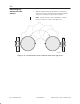


Table Of Contents

1027144–0001 Draft – Revision D.01 6–18 Installing ODUs
RT installation
Check to make sure the radome drain groove is at the bottom of
the antenna.
Figure 6-16 Radome drain groove
Drain
groove
Clamp:
20 inch-pounds
(2.3 Newton-meters)
rt030
If the radome drain groove is at the bottom of the antenna,
proceed to section 6.10.
If the drain groove is not at the bottom of the antenna, rotate the
radome panel as follows:
1. Using a 5/32–inch (4–millimeter) torque hex key wrench,
loosen the radome band clamp locking nut.
2. Rotate the radome panel until the band clamp screw
assembly and drain groove are located at the bottom of the
antenna.
3. Tighten the radome band clamp locking nut to 20
inch–pounds torque (2.3 Newton–meters).
4. Look through the boresight to make sure the antenna is
remains (coarsely) pointed.
Section 6.11 explains how to attach the transceiver to the antenna.
6.9
Checking the
radome drain
position