
Installation Instructions
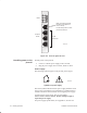
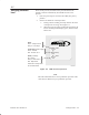

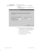
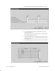
Table Of Contents
- Title page
- Contents
- About this manual
- Safety information
- Ch 1 - Introduction
- Ch 2 - Adding cards to the Controller
- Unpacking the System Controller
- Unpacking the picocells
- System Controller card configuration
- Adding cards to the System Controller (first steps)
- Jumper and DIP switch settings
- Attaching bus cables
- Adding cards to the System Controller (final steps)
- Configuring Controller cards
- Verifying the card configuration
- Ch 3 - Installing the Controller
- Ch 4 - Verifying the Controller configuration
- Ch 5 - Configuring the router
- Ch 6 - Testing picocells
- Ch 7 - Installing picocells
- Ch 8 - Connecting to external equipment
- Ch 9 - System testing
- Ch 10 - Installation inspection
- Ch 11 - Provisioning
- Ch 12 - Remote Client
- Ch 13 - Troubleshooting
- Ch 14 - Maintaining Quad T1 cards
- App A - Specifications
- App B - Standards compliance information
- App C - Part numbers
- App D - Updates and backups
- Index

1026209–0001 Revision B 6–4 Testing picocells
1
2
3
4
T0001007
LEDs
Picocell
connections
All ports:
RJ-45
PBX connection (typically
first port of first Quad T1
card, in slot 9)
For all other Quad T1 cards:
picocell connection
Figure 6-2 Ports on Quad T1 card
Provide power to the picocell:
1. Connect a –48 Vdc power supply to the test cable.
2. Plug the power supply into a 120 Vac, 60 Hz ac outlet.
Power supply
The following symbols appear on the picocell power supply:
Symbols on power supply
T0001023
The house symbol indicates that the power supply should be used
only in a dry environment. The exclamation (!) symbol means to
read the instructions in this manual concerning the power supply.
As stated on the power supply, there are NO USER
SERVICEABLE PARTS INSIDE. Do not attempt to open or
repair the power supply.
For power supply specifications, see Appendix A, Section A.3.
Providing power to the
picocell